Instrument Transformers | Electrical and Electronic Measurements - Electrical Engineering (EE) PDF Download

Instrument Transformer
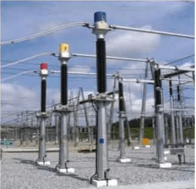
Instrument Transformers are used in AC system for measurement of electrical quantities i.e. voltage, current, power, energy, power factor, frequency. Instrument transformers are also used with protective relays for protection of power system.
Basic function of Instrument transformers is to step down the AC System voltage and current. The voltage and current level of power system is very high. It is very difficult and costly to design the measuring instruments for measurement of such high level voltage and current. Generally measuring instruments are designed for 5 A and 110 V.
The measurement of such very large electrical quantities, can be made possible by using the Instrument transformers with these small rating measuring instruments. Therefore these instrument transformers are very popular in modern power system.
 Advantages of Instrument Transformers
- The large voltage and current of AC Power system can be measured by using small rating measuring instrument i.e. 5 A, 110 – 120 V.
- By using the instrument transformers, measuring instruments can be standardized. Which results in reduction of cost of measuring instruments. More ever the damaged measuring instruments can be replaced easy with healthy standardized measuring instruments.
- Instrument transformers provide electrical isolation between high voltage power circuit and measuring instruments. Which reduces the electrical insulation requirement for measuring instruments and protective circuits and also assures the safety of operators.
- Several measuring instruments can be connected through a single transformer to power system.
- Due to low voltage and current level in measuring and protective circuit, there is low power consumption in measuring and protective circuits.
Types of Instrument Transformers
Instrument transformers are of two types:
- Current Transformer (C.T.)
- Potential Transformer (P.T.)
1. Current Transformer (C.T.)
Current transformer is used to step down the current of power system to a lower level to make it feasible to be measured by small rating Ammeter (i.e. 5A ammeter). A typical connection diagram of a current transformer is shown in figure below.
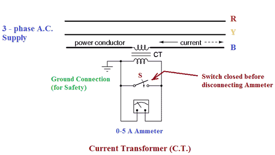
Primary of C.T. is having very few turns. Sometimes bar primary is also used. Primary is connected in series with the power circuit. Therefore, sometimes it also called series transformer. The secondary is having large no. of turns. Secondary is connected directly to an ammeter. As the ammeter is having very small resistance. Hence, the secondary of current transformer operates almost in short circuited condition. One terminal of secondary is earthed to avoid the large voltage on secondary with respect to earth. Which in turns reduce the chances of insulation breakdown and also protect the operator against high voltage. More ever before disconnecting the ammeter, secondary is short circuited through a switch ‘S’ as shown in figure above to avoid the high voltage build up across the secondary.
2. Potential Transformer (P.T.)
Potential transformer is used to step down the voltage of power system to a lower level to make is feasible to be measured by small rating voltmeter i.e. 110 – 120 V voltmeter. A typical connection diagram of a potential transformer is showing figure below.
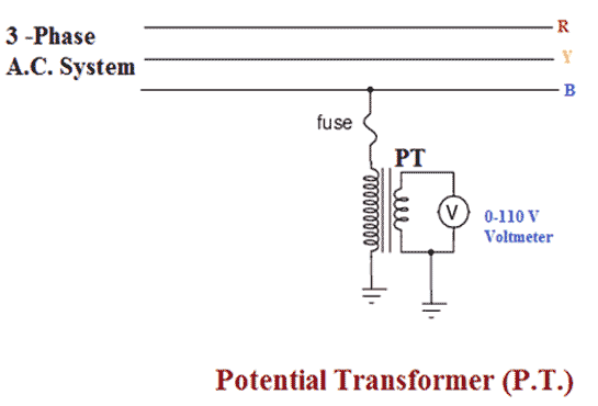
Primary of P.T. is having large no. of turns. Primary is connected across the line (generally between on line and earth). Hence, sometimes it is also called the parallel transformer. Secondary of P.T. is having few turns and connected directly to a voltmeter. As the voltmeter is having large resistance. Hence the secondary of a P.T. operates almost in open circuited condition. One terminal of secondary of P.T. is earthed to maintain the secondary voltage with respect to earth. Which assures the safety of operators.
Difference between C.T. and P.T.
Few differences between C.T. and P.T. are listed below –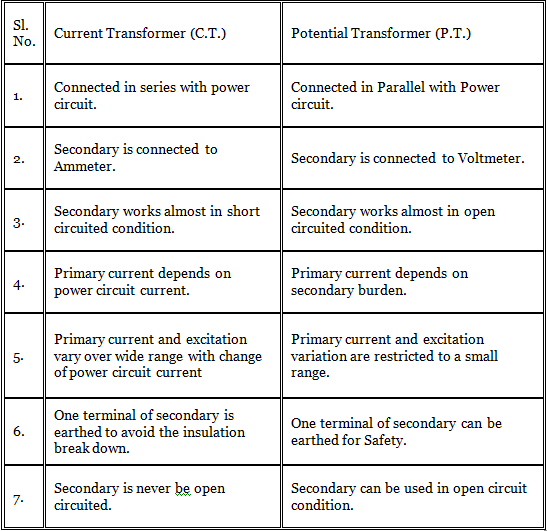
|
48 videos|48 docs|23 tests
|
FAQs on Instrument Transformers - Electrical and Electronic Measurements - Electrical Engineering (EE)
| 1. What is an instrument transformer? |  |
| 2. How does an instrument transformer work? | |
| 3. What are the types of instrument transformers? | |
| 4. What are the applications of instrument transformers? | |
| 5. How to select the appropriate instrument transformer for a specific application? | |


Objective type Questions
,Viva Questions
,Sample Paper
,Instrument Transformers | Electrical and Electronic Measurements - Electrical Engineering (EE)
,MCQs
,mock tests for examination
,past year papers
,ppt
,video lectures
,Important questions
,practice quizzes
,Semester Notes
,Extra Questions
,Exam
,Free
,Instrument Transformers | Electrical and Electronic Measurements - Electrical Engineering (EE)
,shortcuts and tricks
,Instrument Transformers | Electrical and Electronic Measurements - Electrical Engineering (EE)
,Summary
,Previous Year Questions with Solutions
,study material
;


Instrument Transformers Free PDF Download
Importance of Instrument Transformers
Instrument Transformers Notes
Instrument Transformers Electrical Engineering (EE) Questions
Study Instrument Transformers on the App
|
© EduRev
|
Education Revolution
|


|


