Capacitance of Transmission Lines | GATE Notes & Videos for Electrical Engineering - Electrical Engineering (EE) PDF Download
Introduction
Transmission line conductors constitute a capacitor between them. The conductors of the transmission line act as a parallel plate of the capacitor and the air is just like a dielectric medium between them. The capacitance of a line gives rise to the leading current between the conductors. It depends on the length of the conductor.
The capacitance of the line is proportional to the length of the transmission line. Their effect is negligible on the performance of short (having a length less than 80 km) and low voltage transmission line. In the case of high voltage and long lines, it is considered as one of the most important parameters.
Capacitance of two-wire line
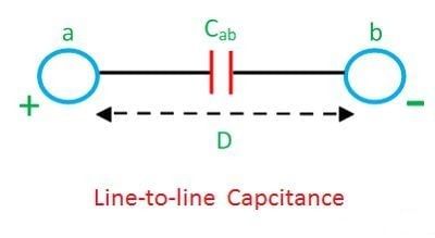
The capacitance of the transmission line along with the conductances forms the shunt admittance. The conductance in the transmission line is because of the leakage over the surface of the conductor. Considered a line consisting of two conductors a and b each of radius r. The distance between the conductors being D shown in the diagram below:-
The potential difference between the conductors a and b is

Where, qa – charge on conductor a
qb – charge on conductor b
Vab – potential difference between conductor a and b
ε- absolute permittivity
qa+qb = 0
so that,
qa = -qb
Dab = Dba = D
Daa = Dbb = r
Substituting these values in voltage equation we get,

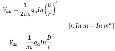
The capacitance between the conductors is

Cab is referred to as line-to-line-capacitance.
If the two conductors a and b are oppositely charged, and the potential difference between them is zero, then the potential of each conductor is given by 1/2 Vab.

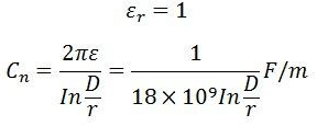
The capacitance between each conductor and point of zero potential n is

Capacitance Cn is called the capacitance to neutral or capacitance to ground.
Capacitance Cab is the combination of two equal capacitance a and b in series. Thus, capacitance to neutral is twice the capacitance between the conductors, i.e.,
Cn = 2Cab
The absolute permittivity ε is given by
ε = εoεr
where εo is the permittivity of the free space and εr is the relative permittivity of the medium.

For air
Capacitance reactance between one conductor and neutral

Capacitance of the symmetrical three-phase line
Let a balanced system of voltage be applied to a symmetrical three-phase-line shown below
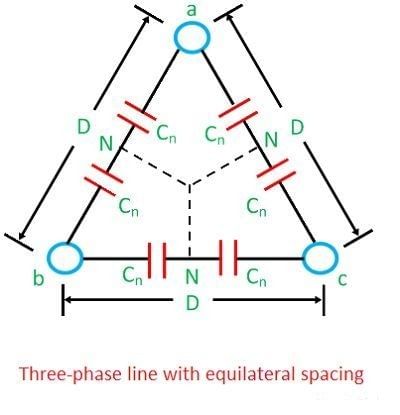
The phasor diagram of the three-phase line with equilateral spacing is shown below:
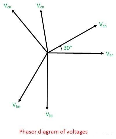
Take the voltage of conductor a to neutral as a reference phasor

The potential difference between conductor a and b can be written as

Similarly, potential difference between conductors a and c is


On adding equations (1) and (2), we get

Also,

Combining equation (3) and (4)


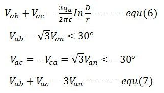
From equation (6) and (7)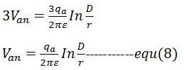
The line-to-neutral capacitance
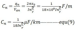
The capacitance of symmetrical three-phase line is same as that of the two-wire line.
|
28 videos|333 docs
|
FAQs on Capacitance of Transmission Lines - GATE Notes & Videos for Electrical Engineering - Electrical Engineering (EE)
| 1. What is capacitance in transmission lines? |  |
| 2. How does capacitance affect the performance of transmission lines? |  |
| 3. What factors affect the capacitance of transmission lines? |  |
| 4. How is capacitance calculated in transmission lines? |  |
| 5. What are the effects of capacitance on signal integrity in transmission lines? |  |


