Performance of Transmission Line & Travelling Wave | Power Systems - Electrical Engineering (EE) PDF Download
Transmission Line
A transmission line is a set of conductors being run from one place to another supported on transmission towers. Therefore, such lines have four distributed parameters, series resistance, inductance shunt capacitance and conductance.
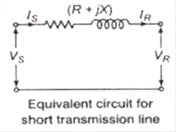
Short Transmission Line
The effect of capacitance is ignored in these lines, length of short transmission line is less than 80 km.
where, Vs = Sending end voltage
ls = Sending end current
VR = Receiving end voltage
IR = Receiving end current
IS = IR
VR +l(R+ jX) = Vs

∴ A =1, B=2,C=0, D=1
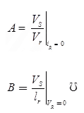
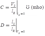
 Two part representation of transmission network

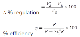
Efficiency

where, P = Power received
Medium Transmission Line
The range of length of this transmission line is 80 km to 250 km. Medium transmission lines are modeled with lumped shunt admittance.
Nomial-π Representation
The lumped series impedance is placed in the middle while the shunt admittance is divided into equal parts and placed at the two ends.

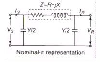
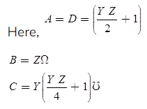
For Voltage Regulation
The no-load receiving end voltage

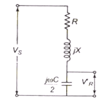
Nomial-π circuit under no load condition
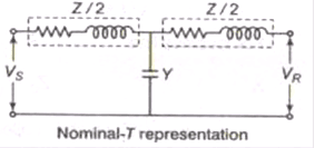
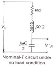
Nominal-T Representation
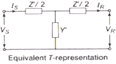
The shunt admittance is placed in the middle and the series impedance is divided into equal parts and these parts are placed on either side of the shunt admittance.
Here,
For Voltage Regulation
The no-load receiving end voltage
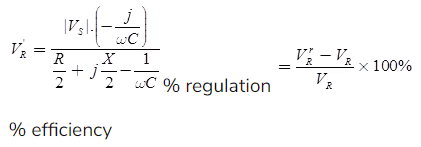

Note: Percentage regulation

Here, |VS| = Sending end voltage |VR.r2| = Full load receiving end voltage.
Long Transmission Line
The length of long transmission line is more than 250 km.
The ABCD parameters of the long transmission line are,
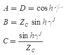
where,

which is called the characteristic impedance

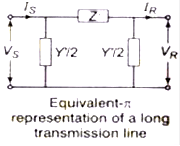
π-Representation of a Long Transmission Line
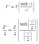
In this, the series impedance is denoted by Zj while the shunt admittance is denoted by Y’
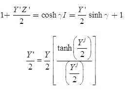
ABCD, parameters are
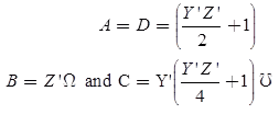
where,


T-Representation of Long Transmission Line
Parameters are

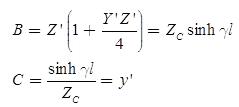
and
Power Flow Through a Transmission Line

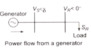
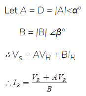

The complex power VR IR at receiving end

The real active power at receiving end,

The reactive power at the receiving end,

For fixed value of VS and VR the receiving end real active power is maximum when

Surge Impedance
This is also known as characteristic impedance. It is impedance offered by the system under surge impedance loading.
Characteristic impedance

Here, Z = Series impedance per unit length
Y = Shunt admittance per unit length
For lossless line, R = 0, G = 0

It can be also given by

where, ZOC = Sending end impedance with receiving end open circuited

ZSC = Sending end impedance with receiving end short-circuited

Propagation Constant

where, α = Attenuation constant
β = Phase constant
Surge Impedance Loading (SIL)
Surge Impedance Loading (SIL) of a line is the power delivered by a line to a purely resistive load equal to its surge impedance.


where, β = Phase shift in red/mile
Key Points
- Surge impedance for the transmission line is 400Ω and for cable, it is 40 Ω.
- The phase angle of surge impedance (ZC) of transmission lines is in range of 0o to -15o.
- If loading of the = SIL, then the power factor will be unity. Hence, maximum power can be transferred and the line can be called as the flat line.
- If loading of line < SIL, then power factor will be leading.
- If loading of line > SIL, then power factor will be lagging.
Wave Phenomenon
Refracted (transmitted) wave = Incident (forward) wave + Reflected wave
VT = VF + VR
where, VT = Refracted (transmitted) voltage wave
VF = Incident or forward voltage wave
VR = Reflected voltage
Transmission Line Termination
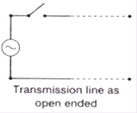
Case (1) Open-Ended Line
- Current becomes at load end zero. Due to this electromagnetic energy
 converted into electrostatic energy
- The potential at the open end becomes 2V.
 where, IT = Transmitted or refracted current wave
IR = Reflected current wave
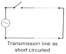
Case (2) Short Circuited Line
- When line is short-circuited at load end, the voltage at load end becomes zero and electrostatic energy is converted into electromagnetic energy
- The current becomes 2l at the short end.
 VT = 0
VR = -VR
IT = 2 / F
IR = IF
Case (3) Termination of Line with Resistor
Coefficient of refraction of voltage

Coefficient of reflection of voltage wave

Coefficient of refraction (transmit) of current wave
Coefficient of refraction of current wave
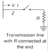
Note: When the terminated by a resistor equal to surge impedance
VT =VF; VR = IT = IF; IR = 0
The incident wave continuous as it is and there is no reflection.
Case (4) Line Terminated by an Inductor
Transmitted (refracted) voltage
Reflected voltage wave
Transmitted (refracted) current wave.
Reflected current wave

Where, Zc = Surge impedance of the line.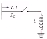 Transmission line terminated by a inductor L
Case (5) Line Terminated by a Capacitor
Transmitted (refracted) voltage wave

Reflected voltage wave

Transmitted (refracted) current wave

Reflected current wave

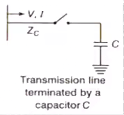
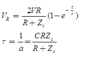
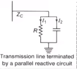
Case (6) Parallel Reactive Termination
Refracted (transmitted) voltage wave,
Transmission Coefficient at T Junction (Forked Line)
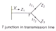
Refraction coefficient

Refracted (transmitted voltage wave)

Line Connected to Cable
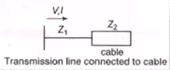
Refracted voltage wave

|
21 videos|67 docs|45 tests
|
FAQs on Performance of Transmission Line & Travelling Wave - Power Systems - Electrical Engineering (EE)
| 1. What is the performance of a transmission line? |  |
| 2. How is impedance important in the performance of a transmission line? |  |
| 3. What is attenuation in the context of a transmission line? |  |
| 4. How does reflection affect the performance of a transmission line? |  |
| 5. What is meant by dispersion in a transmission line? |  |

|
Explore Courses for Electrical Engineering (EE) exam
|

|
 converted into electrostatic energy
 where, IT = Transmitted or refracted current wave
 VT = 0


