Load Flow Analysis | Power Systems - Electrical Engineering (EE) PDF Download
We have already know that the Power flow in a network is determined by the voltage at each bus of the network and the impedances of the lines between buses. Power flow into and out of each of the buses that are network terminals is the sum of power flows of all of the lines connected to that bus.

The load flow problem consists of finding the set of voltages: magnitude and angle, which, together with the network impedances, produces the load flows that are known to be correct at the system terminals. To start, we view the power system as being a collection of buses, connected together by lines. At each of the buses, which we may regard as nodes, we may connect equipment which will supply power to or remove power from the system.
Load flow (or power flow) solution is the determination of current, voltage, active power and reactive volt-amperes at various points in a power system operating under normal steady-state or static conditions.
Short circuits occur in power system due to various reasons like equipment failure, lightning strikes, falling of branches or trees on the transmission lines, switching surges, insulation failures and other electrical or mechanical causes. All these are collectively called faults in power systems.
Bus Classification
Depending upon which two variables are specified a priori, the buses are classified into three categories.

- Load Bus or PQ Bus
At this type of bus, the net powers Pi and Qi are known (PDi and QDi are known from Load forecasting and PGi and QGi are specified). The unknowns are |Vi| and δi. A pure load bus (no generating facility at the bus, i.e., PGi = QGi = 0) is a PQ bus. - PV Bus/Generator Bus/Voltage Controlled Bus
At this type of bus PDi, and QDi, are known a priori and |Vi| and Pi (hence PGi) are specified. The unknowns are Qi (hence QGi) and δi. - Slack Bus/Swing Bus/Reference Bus
This bus is distinguished from the other two types by the fact that real and reactive powers at this bus are not specified. Instead, voltage magnitude and phase angle (normally set equal to zero) are specified.
Note:
- Because in a load flow study real and reactive powers (i.e. complex power) cannot be fixed a priori at all the buses as the net complex power flow into the network is not known in advance, the system power loss being unknown till the load flow study is complete.
- It is, therefore, necessary to have one bus (i.e. the slack bus) at which complex power is unspecified so that it supplies the difference in the total system load plus losses and the sum of the complex powers specified at the remaining buses.
where |V| = Magnitude of voltage
δ = Phase angle of the voltage
P = Active power
Q = Reactive volt-ampere
Bus Admittance Matrix (Ybus)
Load Flow Problem: The complex power injected by the source into the ith bus of a power system is

where Vi is the voltage at the ith bus with respect to ground and Ji is the source current injected into the bus.
The Load Flow analysis is handled more conveniently by use of Ji rather than J*i. Therefore, taking the complex conjugate of last equation, we have
Substituting from

In Polar Form

Real and reactive powers can now be expressed as


where i going from i = 1,2.....n
Equations for Pi & Qi are referred to as static load flow equations (SLFE). By transposing all the variables on one side, these equations can be written in the vector form
f (x, y) = 0
where
f = vector function of dimension 2n
x = dependent or state vector of dimension 2n (2n unspecified variables)
y = vector of independent variables of dimension 2n
(2n independent variables which are specified a priori)
Some of the independent variables in y can be used to manipulate some of the state variables. These adjustable independent variables are called control parameters. Vector y can then be partitioned into a vector u of control parameters and a vector p of fixed parameters.
To study SLFE solution to have practical significance, all the state and control variables must lie within specified practical limits These limits, which are dictated by specifications of power system hardware and operating constraints, are described below
- Voltage magnitude |Vi| must satisfy the inequality
|Vi|min ≤ |Vi| ≤ |Vi|max
The power system equipment is designed to operate at fixed voltages with allowable variations of ± (5 —10)% of the rated values. - Certain of the δis (state variables) must satisfy the inequality constraint
|δi - δk| ≤ |δi - δkmax| - Owing to physical limitations of P and/or Q generation sources, PGi and QGi are constrained as follows

It is, of course, obvious that the total generation of real and reactive power must equal the total load demand plus losses, i.e.
where PL and QL are system real and reactive power loss, respectively.
Formation Zbus or Ybus
Consider a power system network, consisting of two generating stations which is shown in figure below
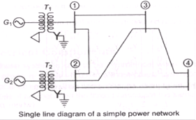
The bus admittance matrix Ybus relates the bus voltage Vbus current fbus through the relation
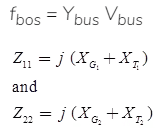
These equations can be written in matrix form as
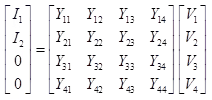
The compact form of these equations can be written as

Bus Impedance Matrix (Zbus)
Bus impedance matrix (Zbus) is the inverse matrix of Ybus (bus admittance matrix)

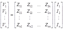
And the relation between Zbus and Vbus is as follows
Vbus = Zbus Ibus
or
Advantage of Ybus over Zbus
- YBUS is a sparse matrix
- Diagonal elements are dominating Off diagonal elements are symmetric.
- Off-diagonal elements are symmetric, the diagonal elements of each node are the sum of the admittances connected to it.
- The diagonal elements of each node are the sum of the admittances connected to it.
- The off-diagonal element is negated admittance.
Development of Load Flow Equations
For n-bus system, the nodal current equation is

where, P = Active power
Q = Reactive power

Substituting for Ip in Eq. (iii),

Ip has been substituted by the real and reactive powers because normally in a power system these quantities are specified.
Acceleration of Convergence in Load Flow Studies
Convergence in the Gauss-Seidel Method can sometimes be speeded up by the use of the acceleration factor. For the ith bus, the accelerated value of voltage at the (r + 1)th iteration is given by

- where α is a real number called the acceleration factor. A suitable value of α for any system can be obtained by trial load flow studies. A generally recommended value is α = 1.6. A wrong choice of cc may indeed slow down convergence or even cause the method to diverge.
- This concludes the load flow analysis for the case of PQ buses only.
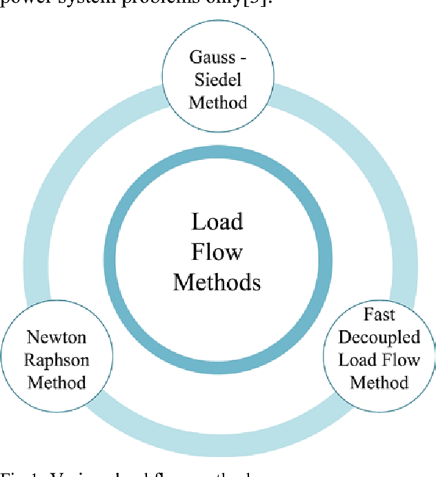
Gauss-Seidel Method
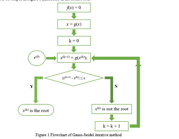
- The Gauss-Seidel Method (GS) is an iterative algorithm for solving a set of non-linear algebraic equations. To start with, a solution vector is assumed, based on guidance from practical experience in a physical situation.
- One of the equations is then used to obtain the revised value of a particular variable by substituting in it the present values of the remaining variables. The solution vector is immediately updated in respect of this variable. The process is then repeated for all the variables thereby completing one iteration.
- The iterative process is then repeated till the solution vector converges within prescribed accuracy. The convergence is quite sensitive to the starting values assumed. Fortunately, in a load flow study, a starting vector close to the final solution can be easily identified with previous experience.
To explain how the Gauss-Seidel Method is applied to obtain the load flow solution, let it be assumed that all buses other than the slack bus are PQ buses. We shall see later that the method can be easily adopted to include PV buses as well. The slack bus voltage being specified, there are (n — 1) bus voltages starting values of whose magnitudes and angles are assumed. These values are then updated through an iterative process.
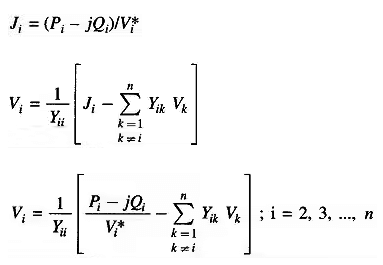
Algorithm for Load Flow Solution
- Presently we shall continue to consider the case where all buses other than the slack are PQ buses. The steps of a computational algorithm are given below
- With the load profile known at each bus (i.e. PDi and QDi known), allocate PGi and QGi to all generating stations. While active and reactive generations are allocated to the slack bus, these are permitted to vary during iterative computation.
- Assembly of bus admittance matrix YBUS: With the line and shunt admittance data stored in the computer, YBUS is assembled by using the rule for self and mutual admittances.
- Iterative computation of bus voltages (Vi; i = 2, 3,…, n): To start the iterations a set of initial voltage values is assumed. Since, in a power system, the voltage spread is not too wide, it is normal practice to use a flat voltage start, e. initially all voltages are set equal to (1 + j0) except the voltage of the slack bus which is fixed.

A significant reduction in the computer time can be achieved by performing in advance all the arithmetic operations that do not change with the iterations.
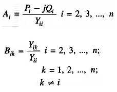
Now for the (r + 1)th iteration, the voltage Equation becomes

The iterative process is continued till the change in magnitude of bus voltage, |ΔVi(r+1)| between two consecutive iterations is less than a certain tolerance for all bus voltages, i.e.

- Computation of slack bus power: Substitution of all bus voltages computed in step 3 along with V1 it yields S1* = P1 — jQ1.
- Computation of line flows: This is the last step in the load flow analysis wherein the power flows on the various lines of the network are computed. Consider the line connecting buses i and The line and transformers at each end can be represented by a circuit with series admittance yik and two shunt admittances yik0 and yki0 as shown in Figure below.
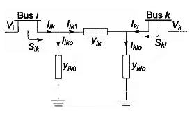
The current fed by bus i into the line can be expressed as
The power fed into the line from bus i is
Similarly, the power fed into the line from bus k is
The power loss in the (i — k)th line is the sum of the power flows determined from Eqs. Sik & Ski. Total transmission loss can be computed by summing all the line flows
(i.e. Sik + Ski for all i, k).
It may be noted that the slack bus power can also be found by summing the flows on the lines terminating at the slack bus.
Algorithm Modification when PV Buses are also Present
At the PV buses, P and |V| are specified and Q and δ are the unknowns to be determined. Therefore, the values of Q and δ are to be updated in every GS iteration through appropriate bus equations. This is accomplished in the following steps for the ith PV bus.
From equation
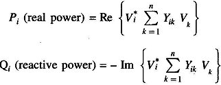
The revised value of Qi is obtained from the above equation by substituting most updated values of voltages on the right-hand side. In fact, for the (r + 1)th iteration one can write from the above equation

The revised value of δi is obtained immediately following step 1. Thus

where

Note: The algorithm for PQ buses remains unchanged.
Newton-Raphson Method
The Newton-Raphson Method is a powerful method of solving non-linear algebraic equations. It works faster and is sure to converge in most cases as compared to the GS method. It is indeed the practical method of load flow solution of large power networks.
Its only drawback is the large requirement of computer memory which has been overcome through a compact storage scheme. Convergence can be considerably speeded up by performing the first iteration through the GS method and using the values so obtained for starting the NR iterations.
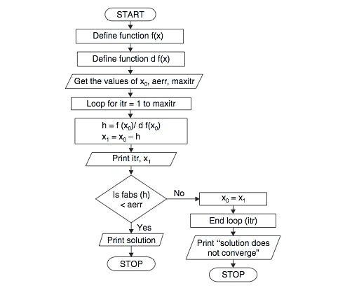 Newton Raphson Method Flowchart
Consider a set of n non-linear algebraic equations
fi(x1,x2, ...., xn) = 0; i=1,2,.....,n
Assume initial values of unknowns as

be the corrections, which on being added to the initial guess, give the actual solution. Therefore

Expanding these equations in Taylor series around the initial guess, we have

where,
are the derivatives if fi with respect to x1,x2,x3,......,xn evaluated at 
Neglecting higher order terms we can write Eqn. in matrix form
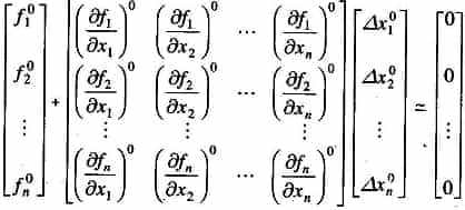
or in vector-matrix form

Jo is known as the Jacobian matrix (obtained by differentiating the function vector f with respect to x and evaluating it at Xo).
Updated values of x are then

or, in general, for the (r+1)th iteration

Iterations are continued it is satisfied to any desired accuracy, i.e.

Comparision of Load Flow Methods
- Gauss-Seidel Method and Newton Raphson methods are compared when both use YBUS as the network model. It is experienced that the Gauss-Seidel Method works well when programmed using rectangular coordinates, whereas Newton Raphson requires more memory when rectangular coordinates are used. Hence, polar coordinates are preferred for the Newton Raphson methods.
- The Gauss-Seidel Method requires the fewest number of arithmetic operations to complete an iteration. This is because of the sparsity of the network matrix and the simplicity of the solution techniques. Consequently, this method requires less time per iteration.
- With the NR method, the elements of the Jacobian are to be computed in each iteration, so the time is considerably longer. For typical large systems, the time per iteration in the NR method is roughly equivalent to 7 times that of the Gauss-Seidel Method. The time per iteration in both these methods increases almost directly as the number of buses of the network.
- The rate of convergence of the Gauss-Seidel Method is slow (linear convergence characteristic), requiring a considerably greater number of iterations to obtain a solution than the NR method which has quadratic convergence characteristics and is the best among all methods from the standpoint of convergence.
- In addition, the number of iterations for the Gauss-Seidel Method increases directly as the number of buses of the network, whereas the number of iterations for the Newton Raphson methods remains practically constant, independent of system size.
- The Newton Raphson methods needs 3 to 5 iterations to reach an acceptable solution for a large system. In the Gauss-Seidel Method and other methods, convergence is affected by the choice of slack bus and the presence of series capacitor, but the sensitivity of the Newton Raphson methods is minimal to these factors which cause poor convergence.
- The chief advantage of the Gauss-Seidel Method is the ease of programming and most efficient utilization of core memory. It is, however, restricted in use of small size system because of its doubtful convergence and longer time needed for the solution of large power networks.
- Thus the Newton Raphson methods is decidedly more suitable than the Gauss-Seidel Method for all but very small systems.
- For FDLF, the convergence is geometric, two to five iterations are normally required for practical accuracies, and it is more reliable than the formal Newton Raphson methods. This is due to the fact that the elements of [B’] and [B”] are fixed approximation to the tangents of the defining functions ΔP/|V| and ΔQ/|V|, and are not sensitive to any ‘humps’ in the defining functions.
- If ΔP/|V| and ΔQ/|V| are calculated efficiently, then the speed for iterations of the FDLF is nearly five times that of the formal Newton Raphson or about two-thirds that of the Gauss-Seidel Method. Storage requirements are around 60 percent of the formal Newton Raphson, but slightly more than the decoupled Newton Raphson methods.
- The FDLF can be employed in optimization studies and is specially used for accurate information of both real and reactive power for multiple load flow studies, as in contingency evaluation for system security assessment and enhancement analysis.
Economic Operation of Power System
The most efficient method involves incremental fuel cost per unit and the incremental fuel cost is the ratio of small change in input to a small change in output.

Economic Loading Neglecting Transmission Losses: To formulate economic loading into mathematical problem, the fuel input curve is modeled as a quadratic equation.
Let the fuel input curve is

where, Fi = Fuel input cost of an unit i in ₹/h
pi = Power output of the unit / in MW
Then, the incremental operating cost of each unit is computed as,

For k unit,

For Two Generating Units
Total cost Fr = F1 + F2
Total output Pr = P1 + P2

Economic Loading Including Transmission Losses: For 2 plants Transmission loss
where, B11, B22 and B12 are called loss coefficients or –coefficients.
For three plant system,

Penalty Factor:

where, Ln = Penalty factor of plant n.
|
30 videos|101 docs|45 tests
|
FAQs on Load Flow Analysis - Power Systems - Electrical Engineering (EE)
| 1. What is the purpose of the Bus Admittance Matrix (Ybus) in load flow analysis? |  |
| 2. How is the Bus Impedance Matrix (Zbus) different from the Bus Admittance Matrix (Ybus) in load flow analysis? |  |
| 3. Why is load flow analysis important in electrical engineering? |  |
| 4. How is the Ybus matrix calculated for a power system? |  |
| 5. What are some common tools or software used for load flow analysis in electrical engineering? |  |


