Switchgear & Protection - 2 | GATE Notes & Videos for Electrical Engineering - Electrical Engineering (EE) PDF Download
Power System Protection and Switch-gear
An electric power system should ensure the availability of electric power without interruption to every load connected to the system. One of the sources of trouble to continuous supply is the shunt fault or short circuit which produces a sudden and sometimes violent change in the system.
Protective relays and relaying system detect abnormal conditions like faults in electric circuits and operate automatic switchgear to isolate faulty equipment from the system as quickly as possible.
Over Current Relay
A relay that operates or picks up when it’s current exceeds a predetermined value (setting value) is called Over Current Relay.
Over current protection protects electrical power systems against excessive currents which are caused by short circuits, ground faults, etc. Over current relays can be used to protect practically any power system elements, i.e. transmission lines, transformers, generators, or motors.
Over current includes short-circuit protection. Short circuits can be Phase faults, Earth faults, Winding faults, Differential and distance protection.
Over current protection is useful for the following:
- Detect abnormal conditions
- Isolate faulty part of the system
- Speed Fast operation to minimize damage and danger
- Discrimination Isolate only the faulty section
- Dependability / reliability
- Security / stability
- Cost of protection / against cost of potential hazards
Type of Over Current Relay
- Instantaneous Over Current (Define Current) Relay
- Define Time Over Current Relay
- Inverse Time Over Current Relay (IDMT Relay): Moderately Inverse, Very Inverse Time, Extremely Inverse
- Directional over Current Relay.
Application of over current relay: Motor protection, Transformer protection, Line protection, Distribution protection
Universal Relay Torque Equation
The universal relay torque equation can be given as

where I = RMS value of current in current coil
V = RMS value of voltage fed to the voltage coil
ϕ = Electrical angle between V and I
T = The maximum torque angle K1, K2 and K3 = Relay constant
K = Mechanical restraining torque
Differential Protection
It is used for transformer and generator protection. It simultaneously compares the phaser difference & magnitude of the current entering & leaving the protected zone. Differential protection is a unit protection, relay works on the principle of Kirchoff's current Law. Measuring element is Current Transformer. The differential current measured between the incoming current and Outgoing current must be negligible current during stable and through fault condition. In case of in zone fault or unstable condition (due to CT saturate) relay will sense the differential current and issue the trip signal.
Applications of Differential protection: Transformer, Generator and Cable Protection. Distance Protection: Distance protection is widely used in the transmission network, its also called impedance protection because relay operates with respect to fault impedance of the transmission line (Z=V/I).
It calculates the apparent impedance of a line with the help of voltage & current input connected to the relay. If measured impedance falls below set impedance trip command is issued to clear the fault.
Measuring element is Current Transformer and Voltage Transformer. Usually relay having 4 zones of the transmission line.
Zone1, Zone2, Zone3 will be forward zones (Towards the Line) and zone 4 will be Reverse zone (Towards the Source).
Impedance Relay
From the universal torque equation, putting K3 = 0 and giving negative sign to voltage term, it becomes,
T=K1I2+K2V2
(neglecting spring torque)
An impedance relay is a voltage restrained over current relay.

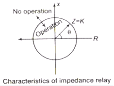
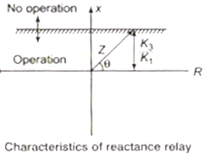
Reactance Relay
In universal torque equation, putting k2 = 0
The reactance relay is direction restrained over current relay.

Mho Relay
In this relay, the operating torque is obtained by the V-I element and
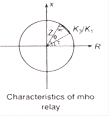
The mho relay is voltage restrained direction relay i.e., this relay has property of inherently directional.

Time Multiplier Setting (TMS)
The time multiplier setting for an inverse time relay is defined as,

Where T = Required time of operation
Tm = The time obtained from the relay characteristics
Plug Setting Multiplier (PSM)
Current setting is adjusted by means of a topped plug bridge, hence known as PSM

Distance protection Scheme
A distance relay has the ability to detect a fault within a pre-set distance along a transmission line or power cable from its location. Every power line has a resistance and reactance per kilometer related to its design and construction so its total impedance will be a function of its length. A distance relay therefore looks at current and voltage and compares these two quantities on the basis of Ohm’s law.

Zones of Protection
In Zone of Protection, Careful selection of the reach point settings and tripping times for various zones of measurement enables correct coordination between distance relays on a power system. Basic distance protection will comprise one instantaneous (Zone 1) and one or more time delayed zones (Zone 2, Zone 3, Zone4 …). Typical reach and time settings for a 3-Zone distance protection are shown below:

- Zone 1: this is set to protect between 80% of the line length AB and operates without any time delay. This “under-reach” setting has been purposely chosen to avoid “over-reaching” into the next line section to ensure selectivity since errors and transients can be present in the voltage and current transformers. Also manufacturing tolerances limit the measurement accuracy of the relays.
- Zone 2: this is set to protect 100% of the line length AB, plus at least 20% of the shortest adjacent line BC and operates with time delay t2. (≈0.5s) It not only covers the remaining of the line, but also provides backup for the next line section.
- Zone 3: this is set to protect 100% of the two lines AB, BC, plus about 25% of the third line CD and operates with time delay t3. (≈1.5s)
Impedance Characteristic
If the relay’s operating boundary is plotted on an R-X diagram, its impedance characteristic is a circle with its center at the origin of the coordinates and its radius will be the setting (the reach point) in ohms. The relay will operate for all values less than its setting i.e. for all points within the circle. This type of relay, however, is non-directional. It can operate for faults behind the relaying point. It takes no account of the phase angle between voltage and current. It is also sensitive to power swings and load encroachment due to the large impedance circle.
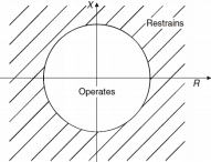
Mho Characteristic
The limitation of the impedance characteristic can be overcome by a technique known as self polarization. Additional voltages are fed into the comparator in order to compare the relative phase angles of voltage and current, so providing a directional feature. This has the effect of moving the circle such that the circumference of the circle passes through the origin. Angle 𝜃 is known as the relay’s characteristic angle. It appears as a straight line on an admittance diagram.


Significance of R-X Diagram
- In general, all electro-mechanical relays respond to one or more of the conventional torque producing input quantities: (a) voltage, (b) current, (c) product of voltage, current and the angle θ between them and (d) a physical or design force such as a control spring.
- Similar considerations hold for solid-state relays as well. For distance relay, analyzing the response of the relay for all conditions is difficult because the voltage varies for each fault, or varies for the same fault but with different system conditions.
- To resolve this difficulty, it is common to use an R–X diagram. By utilizing only two quantities, R and X (or Z and θ), we avoid the confusion introduced by using the three quantities E, I and θ. There is an additional significant advantage in that the R–X diagram allows us to represent both the relay and the system on the same diagram.
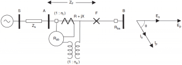
The subscript ‘p’ represents primary and ‘s’ represents secondary quantities. In terms of the secondary quantities of voltage and current transformers, the relay sees Zfp & Zfs as

where ni and ne are the current transformer (CT) and voltage transformer (VT) turns ratios.
Sampling Comparator
There are two methods of comparison: the amplitude and phase comparison techniques.
In amplitude comparison technique, the compactor produces an output whose amplitude is proportional to the amplitude difference of the input quantities;
While in phase comparison technique, the Comparator the phase angles of the input quantities and produces pulses whose width is proportional to the phase difference of the input quantities. The amplitude Comparator can be used as phase Comparator and vice versa, if certain modifications are made.

Instantaneous Comparator (Directing Amplitude Comparator) – Averaging Type
This is then compared with the peak value of operating signal, which may or may not be rectified but is smoothened. The tripping signal is provided if the operating signal exceeds the level of the restraint. Since this method involves smoothening, the operation is slow. A faster method is phase splitting the wave shapes of instantaneous amplitude comparator are shown in fig below before rectification and the averaging circuit can be eliminated.

Phase Comparator
Phase comparison technique is the most widely used one for all practical directional, distance, differential and carrier relays. If the two input signals are S1 and S2 the output occurs when the inputs have phase relationship lying within the specified limits.
Both the input must exist for an output to occur. The operation is independent of their magnitudes and is dependent only on their phase relationship. The figures below show that the phase comparator is simple form. The function is defined by the boundary of marginal operation and represented by the straight lines from the origin of the S-plane.
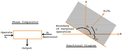
The condition of operation is β1 < θ < β2.
θ is the angle by which S2 lands S1. If β1 = β2 =90o, the comparator is called cosine comparator and if β1=0 and β2=180o, it is a sine comparator.
In short, a phase comparator compares two input quantities in phase angle (vertically) irrespective of the magnitude and operates if the phase angle between them is < 90o.
The Carrier-Current Protection
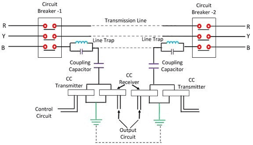
- Carrier current protection scheme is mainly used for the protection of the long transmission line. In the carrier, current protection schemes, the phase angle of the current at the two phases of the line are compared instead of the actual current. And then the phase angle of the line decides whether the fault is internal and external.
- The main elements of the carrier channel are a transmitter, receiver, coupling equipment, and line trap. Line trap is inserted between the bus-bar and connection of coupling capacitor to the line. It is a parallel LC network tuned to resonance at the high frequency. The traps restrict the carrier current to the unprotected section so as to avoid interference from the with or the other adjacent carrier current channels. It also avoids the loss of the carrier current signal to the adjoining power circuit.
Generator Protection - Introduction
No international standards exist regarding the extension of the protective schemes for different types and sizes of generators. The so called "common standard" varies between different countries and also between power companies within the same country, depending on their past experience and different ways in which fault statistics may be interpreted. A relay manufacturer working on the international market should, therefore, be able to offer a protective system which can be easily modified to meet different requirements from different users.
Under certain situations like internal faults, the generator has to be quickly isolated (shut down), while problems like loss of field problem requires an ‘alarm' to alert the operator. Following is a descriptive list of internal faults and abnormal operating conditions.
- Internal Faults
Phase and /or ground faults in the stator and associated protection zone - Ground faults in the rotor (field winding)
Abnormal Operating Conditions
- Overload.
- Overvoltage.
- Loss of field.
- Unbalanced Operation e.g. single phasing.
- Under and over frequency.
- Motoring or loss of prime mover.
- Subsynchronous oscillation.
- Loss of synchronization (out of step).
Protective Relays Used
- Over voltage protection
- Over fluxing protection
- Low forward power and reverse power protection
- Dead machine protection
- Stator over current protection
- Rotor Over current protection
- Generator Loss of excitation protection
- Generator negative phase sequence protection
- Back up distance protection
- Shaft damage protection
- Under frequency protection
- Generator pole slipping protection
- UAT breaker failure protection
Protection Schemes Used
- Generator differential
- Generator and generator transformer overall differential
- Transformer (GT-UAT) differential
- Inter turn fault
- Generator rotor earth fault
- Generator stator earth fault
- UAT differential
- Generator transformer restricted earth fault
- Fire protection for GT and UAT
Stator Earth Fault Protection
Earth fault protection must be applied where impedance earthing is employed that limits the earth fault current to less than the pick-up threshold of the overcurrent and/or differential protection for a fault located down to the bottom 5% of the stator winding from the starpoint. The type of protection required will depend on the method of earthing and connection of the generator to the power system.
Step-up Transformer: Differential Protection
The generator stator and step-up transformer can be protected by a single zone of overall differential protection. This will be in addition to differential protection applied to the generator only. The current transformers should be located in the generator neutral connections and in the transformer HV connections. Alternatively, CT’s within the HV switchyard may be employed if the distance is not technically prohibitive. Even where there is a generator circuit breaker, overall differential protection can still be provided if desired.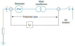
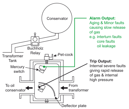
Internal faults in oil filled transformers
In oil filled transformers, internal faults may be classified as follow:
- Faults generating production of gases, mainly:
- Micro arcs resulting from incipient faults in the winding insulation
- Slow degradation of insulation materials
- Inter turns short circuit
- Faults generating internal over pressures with simultaneously high level of line over currents:
- Phase to earth short circuit
- Phase to Phase short circuit.
These faults may be the consequence of external lightning or switching over voltage.
Depending on the type of the transformer, there are two kinds of devices able to detect internal faults affecting an oil filled transformer.
- The Buchholz Relay dedicated to the transformers equipped with an air breathing conservator.
The buchholz relay is installed on the pipe connecting the tank of he transformer to the conservator. It traps the slow emissions of gasses and detect the flow back of oil due to the internal over pressures
Unit Transformer Differential Protection
The current taken by the unit transformer must be allowed for by arranging the generator differential protection as a three-ended scheme. Unit transformer current transformers are usually applied to balance the generator differential protection and prevent the unit transformer through current being seen as differential current.
Overloads and internal faults in dry type transformers
The dry type transformers are protected against over-heating due to possible downstream overloads by a dedicated relay monitoring thermal sensors embedded in the windings of the transformer.
The internal faults, mainly inter turns and phase to earth short circuits occurring inside a dry type transformers are cleared either by the circuit breaker or the fuses installed on the primary side of the transformer. The tripping of the circuit breakers when used is ordered by the phase to phase and phase to earth over current protections.
Inter turns faults need a dedicated attention:
- They generally generate moderate line over currents. As an example when 5 % of a HV winding are short circuited the line current of the transformer does not exceed 2 In, for a short circuit affecting 10 % of the winding the line current is limited around 3 In.
Busbar Protection
Busbars have often been left without specific protection, for one or more of the following reasons:
- The busbars and switchgear have a high degree of reliability, to the point of being regarded as intrinsically safe.
- It was feared that accidental operation of busbar protection might cause widespread dislocation of the power system, which, if not quickly cleared, would cause more loss than would the very infrequent actual bus faults.
- it was hoped that system protection or back-up protection would provide sufficient bus protection if needed.
Types of Protection Scheme
A number of busbar protection systems have been devised:
- System protection used to cover busbars
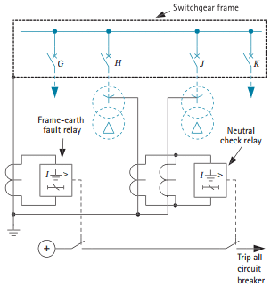
- Frame-earth protection
- Differential protection
- Phase comparison protection
- Directional blocking protection
Single-Busbar Frame-Earth Protection
This is purely an earth fault system and, in principle, involves simply measuring the fault current flowing from the switchgear frame to earth. A current transformer is mounted on the earthing conductor and is used to energize a simple instantaneous relay.
- The principal earth connection and current transformer are not shunted, thereby raising the effective setting. An increased effective setting gives rise to the possibility of relay maloperation. This risk is small in practice.
- Earth current flowing to a fault elsewhere on the system cannot flow into or out of the switchgear frame via two earth connections, as this might lead to a spurious operation.
Circuit Breaker
- Circuit breakers are critical to the safe operation of an electrical grid. They are needed in electricity generators, where the full power of an entire power plant (gigawatts of electricity) must be switched on and off, and on transmission lines in substations to direct the power flow at voltages in excess of 1500 kV. Circuit breakers are also critical components in distribution grids, where very high currents need to be managed at moderate voltage levels.
- A circuit breaker, irrespective of its position in a grid has two tasks: it is responsible for the daily switching of lines during normal operation, and for the disconnection of the power supply in case of overload or short circuit. Several GVA of power can be tamed by a circuit breaker within fractions of a second.
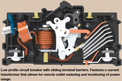
A circuit breaker should be capable of opening on the occurrence of a fault and clearing the fault. It should be closed on to a fault. It should be capable of carrying fault current for a short time while another circuit breaker is clearing the fault.
A circuit-breaker rated at In = 125 A for an ambient temperature of 40°C will be equipped with a suitably calibrated overcurrent tripping relay (set at 125 A). The same circuit-breaker can be used at higher values of ambient temperature, however, if suitably “derated”. Thus, the circuit-breaker in an ambient temperature of 50°C could carry only 117 A indefinitely, or again, only 109 A at 60°C, while complying with the specified temperature limit.
Derating a circuit-breaker is achieved, therefore, by reducing the trip-current setting of its overload relay, and marking the CB accordingly. The use of an electronic-type of tripping unit, designed to withstand high temperatures, allows circuit-breakers (derated as described) to operate at 60°C (or even at 70°C) ambient.
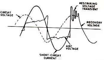
Restriking voltage
Where V = Restriking voltage
Vm = Peak voltage at the instant of are interruption
L = Inductance per phase of the system
C = Capacitance per phase of the system
Natural frequency of oscillation
Rate of Rising of Restriking Voltage (RRRV)


RRRV is maximum
at


Resistance Switching
Frequency of damped oscillation,
if  is known as critical resistance
if  there will be oscillation
if  there will be no transient oscillation
Breaking Current
The symmetrical breaking current of a circuit breaker is the current which it will interrupt at a power factor of 0.15 for railing up to 500 MVA and a power factor of 0.3 for 750 MVA with a recovery voltage of 95% of normal voltage.
Asymmetrical breaking current of a circuit breaker is the current which it will interrupt when there is symmetrical component, its peak value  let
let  then asymmetrical breaking current (I) may be calculated as
Making Capacity
The (peak) making current of a circuit breaker is the peak value of maximum current in the first cycle of current after the current is closed by the current breaker.
Rated (peak) making current = 2.55 × rated asymmetrical breaking capacity.
Short Time Operated Duty
Any Circuit breaker must be capable of the following duty B – 3’ – MB – 3’ – MB
Where B = breaking operations
MB = making operations
3’ = 3 = min time interval
Types of Circuit Breaker
- Oil circuit breaker
- Minimum oil circuit breaker
- Bulk oil circuit breaker
- Air blast circuit breaker
- Sulphur hexa fluoride circuit breaker
- Vacuum circuit breaker
Electric Arc Model for SF6 Circuit Breaker
The characteristics of vacuum as medium and cost of the vacuum CB does not makes it suitable for voltage exceeding 38 kV. These days for higher transmission voltage levels SF6 Circuit Breakers are largely used. OCB and ABCB have almost become obsolete. In fact, in many installations, SF6 CB is used for lower voltages like 11 kV, 6 kV etc..
Sulphur Hexafluoride symbolically written as SF6 is a gas which satisfies the requirements of an ideal arc interrupting medium. So SF6 is extensively used these days as an arc interrupting medium in circuit breakers ranging from 3 kV upto 765 kV class. In addition to this SF6 is used in many electrical equipments for insulation. Here first we discuss in brief, some of the essential properties of SF6 which is the reason of its extensive use in circuit breakers
- SF6 gas has high dielectric strength which is the most important quality of a material for use in electrical equipments and in particular for breaker it is one of the most desired properties. Moreover, it has high Rate of Rising of dielectric strength after arc extinction. This characteristic is very much sought for a circuit breaker to avoid Restriking.
- SF6 is colorless, odorless and non-toxic gas.
- SF6 is an inert gas. So in normal operating condition, the metallic parts in contact with the gas are not corroded. This ensures the life of the breaker and reduces the need for maintenance.
- The characteristics of vacuum as medium and cost of the vacuum CB does not makes it suitable for voltage exceeding 38 kV.
- SF6 has high thermal conductivity which means the heat dissipation capacity is more. This implies greater current carrying capacity when surrounded by SF6 .
- The gas is quite stable. However, it disintegrates to other fluorides of Sulphur in the presence of arc. but after the extinction of the arc, the SF6 gas is reformed from the decomposition.
- SF6 being non-flammable so there is no risk of fire hazard and explosion.
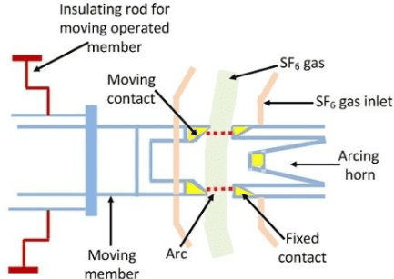
(Transient Recovery Voltage) TRV is the voltage across the opening contacts of a fault-interrupting circuit breaker (CB) immediately after the electric arc is extinguished For calculation of the initial part of TRV, the modeling of the arc resistance in a SF6 CB is important, because it has a significant impact on the TRV. Black box models use a mathematical description of the electrical behavior of an electrical arc. These types of models do not give full representation of the physical processes taking place inside the CB. Recorded voltage and current traces during the "thermal period" are used to obtain the CB parameters that are later on substituted in differential equations.

Vacuum Circuit Breaker
- The vacuum circuit breaker is mainly restricted to system voltage below 38 kV.
- In a Vacuum circuit breaker, vacuum interrupters are used for breaking and making load and fault currents. When the contacts in vacuum interrupter separate, the current to be interrupted initiate a metal vapour arc discharge and flows through the plasma until the next current zero.
- The arc is then extinguished and the conductive metal vapour condenses on the metal surfaces within a matter of microseconds. As a result, the dielectric strength in the breaker builds up very rapidly.
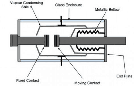
- The properties of a vacuum interrupter depend largely on the material and form of the contacts. Over the period of their development, various types of contact material have been used. At the moment it is accepted that an oxygen-free copper chromium alloy is the best material for High voltage circuit breaker.
- In this alloy, chromium is distributed through copper in the form of fine grains. This material combines good arc extinguishing characteristic with a reduced tendency to contact welding and low chopping current when switching inductive current. The use of this special material is that the current chopping is limited to 4 to 5 Amps.
Medium Voltage Oil Circuit Breakers
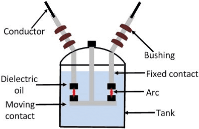
- The following suggestions are for use in conjunction with the manufacturer’s instruction books for the maintenance of medium-voltage oil circuit breakers:
- Check the condition, alignment, and adjustment of the contacts. Thoroughly clean the tank and other parts which have been in con tact with the oil.
- Test the dielectric strength of the oil and filter or replace the oil if the dielectric strength is less than 22 kV. The oil should be filtered or replaced whenever a visual inspection shows an excessive amount of carbon, even if the dielectric strength is satisfactory.
- Check breaker and operating mechanisms for loose hardware and missing or broken cotter pins, retain ing rings, etc.
- Before replacing the tank, check to see there is no friction or binding that would hinder the breaker’s operation. Also, check the electrical operation.
- Avoid operating the breaker any more than necessary without oil in the tank as it is designed to operate in oil and mechanical damage can result from excessive operation without it. When replacing the tank and refilling it with oil, be sure the gaskets are undamaged and all nuts and valves are tightened properly to prevent leak age.
Air Blast Circuit Breaker
The other type of circuit breaker that we discuss here is Air Blast Circuit Breaker(ABCB). This type of breakers is also becoming obsolete. Once Air Blast type of breakers was preferred in Extra High Voltage substations. Now it is difficult to find new HV/EHV substations equipped with Air Blast Circuit Breakers.
Note: One should not be confused between Air Circuit Breaker and Air Blast Circuit Breaker.
- Air Circuit Breakers are usually used in low voltage applications below 450 volts. You can today find these in Distribution Panels (below 450 volts).
- Air Blast Circuit Breakers are high capacity breakers and can be seen in old substations mainly above 132 kV. The working principle of these two circuit breakers is quite different. Here we will only discuss the working of ABCB.
- In Air Blast Circuit Breaker, air at high pressure is blast upon the arc formed between the contacts. The air blast blows away the ionized air between the contacts.
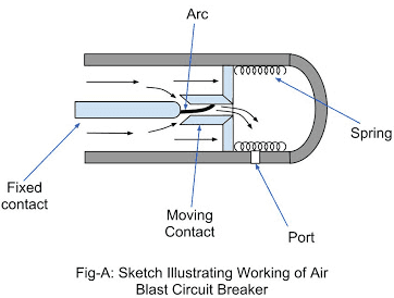
See the Sketches below illustrating the arc extinction process of the axial blast type breaker.
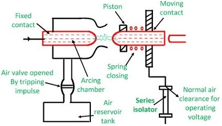
Advantages of the Air Blast Circuit Breaker(ABCB)
- Arc extinction is very fast. Hence it is suitable for frequent opening and closing operation.
- Due to refilling of separated contacts space by fresh air at high pressure, the separation requirement between the contacts is quite less in comparison to OCB. This makes the size of the breaker smaller.
- The ionized gas flushed out to the atmosphere. Hence unlike OCB here the arc quenching medium does not deteriorate with time. This eliminates some maintenance burden.
- It is non-inflammable.
- Finally, one important advantage is that in ABCB the arc quenching depends on the high-pressure air which is obtained from a compressor, an external source. So in case of ABCB, the arc extinction or arcing time does not depend upon the arc current. (In case of OCB the arcing time depends on the current to be interrupted).
- The breaker breaking capacity depends upon the external source, the high-pressure air.
Minimum Oil Circuit Breaker
The simplified constructional diagram of a Minimum Oil Circuit Breaker (MOCB) is shown in the figure. It consists of two oil-filled chambers namely upper chamber and lower chamber, which are separated from each other.
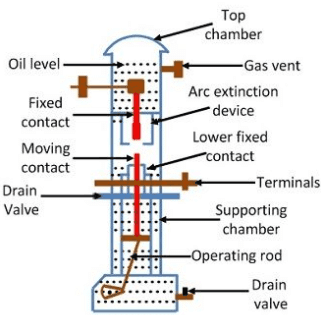
The arc extinction process is carried out in the upper chamber. So, it is called as an arc extinction chamber or current interruption chamber of Minimum Oil Circuit Breaker (MOCB).This chamber houses an arc control device, an upper fixed contact, and a ring-shaped lower fixed contact.
The arc control device is fitted to the upper to the upper fixed contact. The moving contact slides through the lower fixed contact such that a physical (or electrical) maintained between them. The entire assembly of upper fixed contact. lower fixed contact and arc control device is enclosed in a glass fiber enclosure which is surrounded by oil.
Applications of Minimum Oil Circuit Breaker
- For indoor applications, minimum oil circuit breakers can be used up to 36 kV.
- For outdoor applications, minimum oil circuit breakers can be employed upto the line voltages of 220 kV.
|
27 videos|333 docs
|
FAQs on Switchgear & Protection - 2 - GATE Notes & Videos for Electrical Engineering - Electrical Engineering (EE)
| 1. What is power system protection and why is it important? |  |
| 2. What are the main components of switchgear? |  |
| 3. How does switchgear provide protection in a power system? |  |
| 4. What are the different types of switchgear? |  |
| 5. How is switchgear tested for reliability and performance? |  |


