Inductive Circuits | Electricity & Magnetism - Physics PDF Download
Introduction
The ability of a conductor to induce voltage in itself when the current changes is its self-inductance or simply inductance. The symbol for inductance is L, and its unit is the henry (H). One henry is the amount of inductance that permits one volt to be induced when the current changes at the rate of one ampere per second. The formula for inductance is where L = inductance, H
vL = induced voltage across the coil, V
Δi /Δt = rate of change of current, A/s
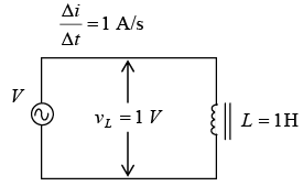 The inductance of a coil is 1H when a change of 1 A/s induces IV across the coil.
The self-induced voltage vL from) is  When the current in a conductor or coil changes, the varying flux can cut across any other conductor or coil located nearby, thus inducing voltages in both. A varying current in L1, therefore, induces voltages across L1 and across L2 (as shown in figure below). When the induced voltage vL2 produces current in L2 , its varying magnetic field induces voltage in L1 . Hence, the two coils L1 and L2 have mutual inductance because current change in one coil can induce voltage in the other. The unit of mutual inductance is the henry, and the symbol is LM . Two coils have LM of 1H when a current change of 1 A/s in one coil induces 1 V in the other coil.
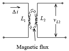 Mutual inductance Between L1 and L2
The schematic symbol for two coils with mutual inductance is shown in figure below.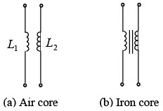
➤ Inductive Reactance
Inductive reactance XL is the opposition to ac current due to the inductance in the circuit. The unit of inductive reactance is the ohm. The formula for inductive reactance is
XL = 2πfL
Since 2π = 2 (3.14) = 6.28, XL = 6.28fL
where = inductive reactance, Ω, f = frequency Hz, L = inductance, H
If any two quantities are known the third can be found
 In a circuit containing only inductance (as shown in figure below, Ohm’s law can be used to find current and voltage by substituting X L for R.
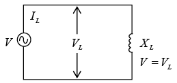 Circuit with only XL
where
IL = current through the inductance, A L
VL = voltage across the inductance, V
XL = inductive reactance, Ω
➤ Inductors in Series or Parallel
If inductors are spaced sufficiently far apart so that they do not interact electromagnetically with each other; their values can be combined just like resistors when connected together. If a number of inductors are connected in series (as shown in figure below), the total inductance LT is the sum of the individual inductances, or
Series: LT = L1 + L2 + L3 +... + Ln Inductances in series without mutual coupling If two series-connected coils are spaced close together so that their magnetic field lines interlink, their mutual inductance will have an effect on the circuit. In that case the total inductance is LT = L1 + L2 ± 2LM
where LM is the mutual inductance between the coils. The plus (+) sign is used if the coils are arranged in series-aiding form, while the minus (-) sign is used if the coils are connected in series-opposing form. Series aiding means that the common current produces the same direction of magnetic field for the two coils. The series-opposing connection results in opposite fields.
Three different arrangements for coils L1 and L2 are shown both pictorially and schematically as shown in figure below. In figure a coils are spaced too far apart to interact electromagnetically. There is no mutual inductance, so LM is zero. The total inductance is LT = L1 + L2. In figure b, the coils are spaced close together and have windings in the same direction, as indicated by the dots. The coils are series-aiding, so
LT = L1 + L2 + 2LM. In figure c, the coil windings are in the opposite direction, so the coils are series-opposing, and LT = L1 + L2 − 2LM .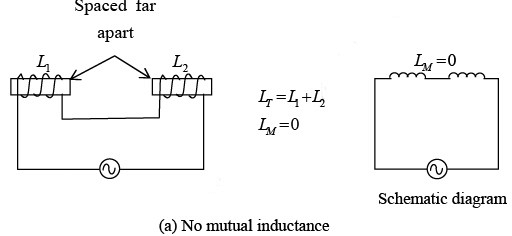
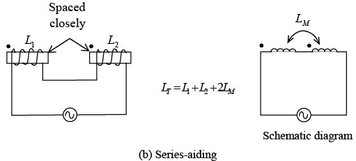
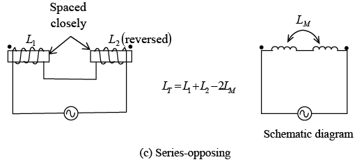
The large dots above the coil (figure b and c) are used to indicate the polarity of the windings without having to show the actual physical construction. Coils with dots at the same end (figure b) have the same polarity or same direction of winding. When current enters the dotted ends for L1 and L2 , their fields are aiding and LM has the same sense as L.
If inductors are spaced sufficiently far apart so that their mutual inductance is negligible ( LM = 0), the rules for combining inductors in parallel are the same as for resistors. If a number of inductors are connected in parallel (as shown in figure below), their total inductance LT is
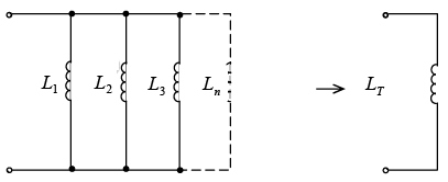 Inductances in parallel without mutual coupling
The total inductance of two coils connected in parallel is All inductances must be given as the same units. The shortcuts for calculating parallel R can be used with parallel L. For example, if two 8-mH inductors are in parallel, the total inductance is LT = L / n = 8 / 2 = 4 mH.
Inductive Circuits
- Inductance Only
If an ac voltage v is applied across a circuit having only inductance (figure a), the resulting ac current through the inductance, iL , will lag the voltage across the inductance, vL , by 90° (figure b and c). Voltage v and vL are the same because the total applied voltage is dropped only across the inductance. Both iL and vL are sine waves with the same frequency. Lowercase letters such as i and v indicate instantaneous values; capital letters such as I and V show dc or ac rms values.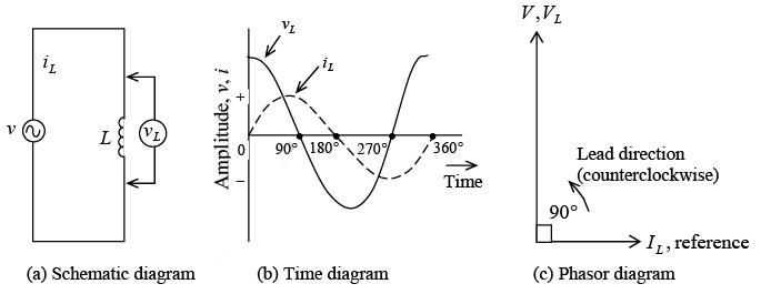 Circuit with L only
 - RL in Series
When a coil has series resistance (figure a shown below), the rms current I is limited by both XL and R . I is the same in XL and R since they are in series. The voltage drop across R is VR =IR, and the voltage drop across XL is VL = IXL. The current I through XL must lag VL by 90° because this is the phase angle between current through an inductance and its self-induced voltage (figure b). The current I through R and its IR voltage drop are in phase so the phase angle is 0°.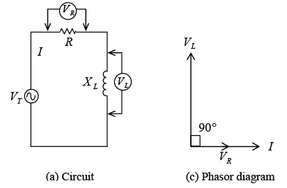 R and XL in series
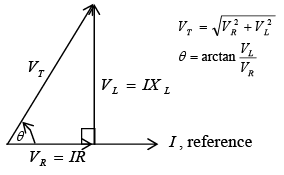 Phasor-voltage triangleTo combine two waveforms out of phase, we add their equivalent phasors. The method is to add the tail of one phasor to the arrowhead of the other, using the angle to show their relative phase. The sum of the phasors is a resultant phasors from the start of one phasor to the end of the other phasor. Since VR and VL phasors form a right angle, the resultant phasor is the hypotenuse of a right triangle. From the geometry of a right triangle, the resultant is
 where the total voltage VT is the phasor sum of the two voltages VR and VL that are 90° out of phase. All the voltages must be in the same units-rms values, peak values, or instantaneous values. For example, when VT is an rms value, VR and VL also are rms values. Most of the ac calculations will be made in rms units.
The phase angle θ between VT and VR is ➤ Impedance in Series RL
Phasor addition of R and XL to find Z
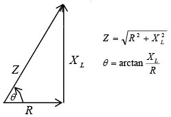
The resultant of the phasor addition of R and X L is called impedance. The symbol for impedance is Z. Impedance is the total opposition to the flow of current, expressed in ohms. The impedance triangle (as shown in figure) corresponds to the voltage triangle, but the common factor I cancels. The equations for impedance and phase angle are derived as follows: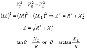 0
0 - RL in Parallel
For parallel circuits with R and XL (figure a shown below), the same applied voltage VT is across R and XL since both are in parallel with VT. There is no phase difference between these voltages. Therefore VT will be used as the reference phasor. The resistive branch current IR = VT / R is in phase with VT . The inductive branch current IL = VT / XL lags VT by 90° (figure b) because the current in an inductance lags the voltage across it by 90° . The phasor sum of IR and IL equals the total line current IT (figure c), or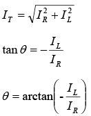
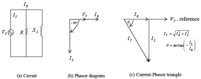 R and XL in parallel
➤ Impedance in Parallel RL
For the general case of calculating the total impedance ZT of R and XL in parallel, assume any number for the applied voltage VT because in the calculation of ZT in terms of the branch currents the value of VT cancels. A convenient value to assume for VT is the value of either R or XL , whichever is the higher number. This is only one method among others for calculating ZT. - Q of a Coil
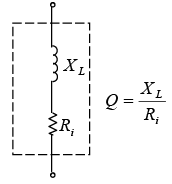
Schematic diagrm of Q of a coil. XL and Ri are distributed uniformly over the length of the coil
The quality or merit Q of a coil is indicated by the equation where Ri is the internal resistance of the coil equal to the resistance of the wire in the coil (figure a). Q is a numerical value without any units since the ohms cancel in the ratio of reactance to resistance. If the Q of a coil is 200, it means that the XL of the coil is 200 times more than its Ri. The Q of a coil may range in the value from less than 10 for a low-Q coil up to 1000 for a very high Q coil. Radio frequency (RF) coils have a Q of about 30 to 300.
As an example, a coil with an XL of 300 Ω and a Ri of 3Ω has a Q of 300/3 =100. - Power in RL Circuit
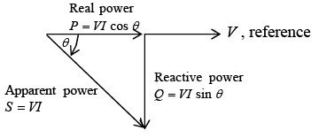 Power triangle for RL circuit
In an ac circuit with inductive reactance, the line current I lags the applied voltage V. The real power P is equal to the voltage multiplied by one that portion of the line current which is in phase with the voltage.
Therefore, Real power P = V(I cosθ) = VI cosθ
where θ is the phase angle between V and I, and cosθ is the power factor (PF) of the circuit. Also, Real power P = I 2 R
where R is the total resistive component of the circuit.
Reactive power Q in voltamperes reactive (VAR), is expressed as follows: Reactive power Q = VI sinθ
Apparent power S is the product of V x I. The unit is voltamperes (VA).
In formula form, Apparent power S = VI In all the power formulas, the V and I are in rms values. The relationships of real, reactive and apparent power can be illustrated by the phasor diagram of power (as shown in above figure).
|
82 videos|32 docs|22 tests
|
FAQs on Inductive Circuits - Electricity & Magnetism - Physics
| 1. What is an inductive circuit? |  |
| 2. What is the significance of inductive circuits in IIT JAM exam? |  |
| 3. How can I analyze inductive circuits in IIT JAM exam? |  |
| 4. What are some common problems or examples related to inductive circuits that can be asked in the IIT JAM exam? |  |
| 5. Are there any specific tips or strategies to prepare for inductive circuits in the IIT JAM exam? |  |


