Single Phase Circuits | Electricity & Magnetism - Physics PDF Download

➤ RLC in Series
Current in a series circuit containing resistance, inductive reactance, and capacitive reactance (figure a shown below) is determined by the total impedance of the combination. The current I is the same in R, XL, and XC since they are in series. The voltage drop across each element is found by Ohm’s law: VR = IR, VL = IXL , VC = IXC
Where VR = voltage drop across the resistance, V
VL = voltage drop across the inductance, V
VC = voltage drop across the capacitance, V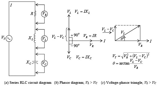 R, XL, and XC in series; XL > XC for inductive circuitThe voltage drop across the resistance is in phase with current through the resistance (figure b shown above). The voltage across the inductance leads the current through the capacitance by 90°. The voltage across the capacitance lags the current through the capacitance by 90° . Since VL and VC are exactly 180° out of phase and acting in exactly opposite directions, they are added algebraically. When XL is greater than XC the circuit is inductive, VL is greater than VC and I lags VT (figure c shown below). When XC is greater than XL, the circuit is capacitive. Now VC is greater than VL so that I leads VT (figure shown below)
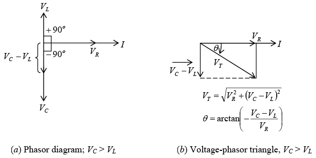 R, XL, and XC in series; XC > XL for capacitive circuitWhen XL > XC, the voltage-phasor diagram shows that the total voltage VT and phase angle are as follows:
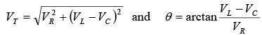 When XC > XL
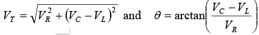 ➤ Impedance in Series RLC
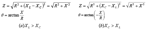
Impedance Z is equal to the phasor sum of R, XL, and XC. In figure a shown below:
When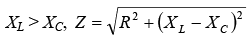 In figure b shown below:When
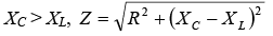 It is convenient to define net reactance X as X = XL – XC
Then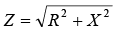 for both inductive and capacitive RLC series circuits.
 ➤ RLC in Parallel
A three- branch parallel ac circuit (figure a shown below) has resistance in one branch, inductance in the second branch, and capacitance in the third branch. The voltage is the same across each parallel branch, so VT = VR = VL = VC. The applied voltage VT is used as the reference line to measure phase angleθ . The total current IT is the phasor sum of IR, IL, and IC. The current in the resistance IR is in phase with the applied voltage VT (figure b shown below). The current in the inductance IL lags the voltage VT by 90°. The current in the capacitor IC leads the voltage VT by 90°. IL and IC are exactly 180° out of phase and thus acting in opposite directions. When IL >IC, IT lags VT (figure c shown below) so the parallel RLC circuit is considered inductive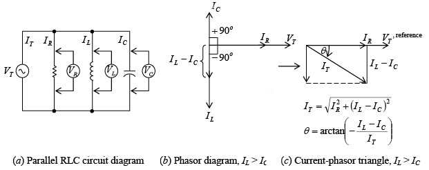 R, XL, and XC in parallel; IL > IC for inductive circuit
If IC > IL, the current relationship and phasor triangle (figure shown below) show that IT now leads VT so this type of parallel RLC circuit is considered capacitive.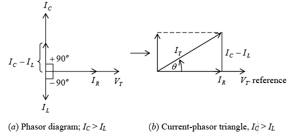 R, XL, and XC in parallel; IC > IL for capacitive circuitWhen IL > IC the circuit is inductive and
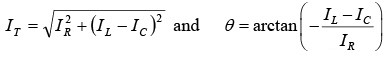 and when IC > IL, the circuit is capacitive and
Note: In a parallel RLC circuit, when XL > XC, the capacitive current will be greater than the inductive current and the circuit is capacitive. When XC > XL, the inductive current is greater than the capacitive current and the circuit is inductive. These relationships are opposite to those for a series RLC circuit.
➤ Impedance in Parallel RLC
The total impedance ZT of a parallel RLC circuit equals the total voltage VT divided by the total current IT.
➤ RL and RC in Parallel
Total current IT for a circuit containing parallel branches of RL and RC (figure shown below) is the phasor sum of the branch currents I1 and I2. A convenient way to find IT is to
(1) Add algebraically horizontal components of I1 and I2 with respect to the phasor reference VT,
(2) Add algebraically the vertical components of I1 and I2, and
(3) Form a right triangle with these two sums as legs and calculate the value of the hypotenuse (IT) and its angle to the horizontal.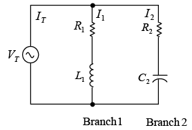 Parallel RL and RC branches
➤ Power and Power Factor
The instantaneous power p is the product of the current i and the voltage v at that instant of time t.
p = vi
When v and i are either positive or both negative, their product p is positive. Therefore, power is being expended throughout the cycle (figure a shown below). If v is negative while i is positive during any part of the cycle (figure b shown below), or if i is negative while v is positive, their product will be negative. This “negative power” is not available for work; it is power returned to the line.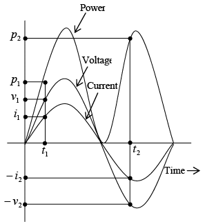 (a): Power-time diagram when voltage and current are in phase
 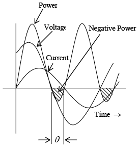 (b): Power-time diagram in series RL circuit where current lags voltage by phase angle θ
The product of the voltage across the resistance and the current through the resistance is always positive and is called real power. Real power can be considered as resistive power that is dissipated as heat. Since the voltage across a reactance is always 90° out phase with the current through the reactance, the product px = vxix is always negative. This product is called reactive power and is due to the reactance of a circuit. Similarly, the product of the line voltage and the line current is known as apparent power. Real power, reactive power, and apparent power can be represented by a right triangle (figure a shown below). From this triangle the power formulas are:
Real power P= VR IR = VI cosθ, W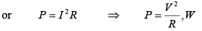
Reactive power Q = Vx Ix = VI sinθ, VAR
Apparent power S = VI , VA
With line voltage V as reference phasor, in an inductive circuit, S lags P (figure b shown below); while in a capacitive circuit, S leads P (figure c shown below).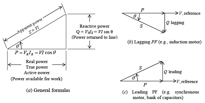 Power triangleThe ratio of real power to apparent power, called the power factor (PF), is Real powe
 Also
Also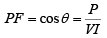 The cos θ of a circuit is the power factor, PF, of the circuit. The power factor determines what portion of apparent power is real power and can vary from 1 when the phase angle θ is 0°, to 0 when θ is 90°. Whenθ = 0° , P = VI, the formula for voltage and current of circuit in phase. Whenθ = 90° , P = VI × 0 = 0, indicating that no power is being expended or consumed.A circuit in which the current lags the voltage (i.e. an inductive circuit) is said to have a lagging PF; a circuit in which the current leads the voltage (i.e., a capacitive circuit) is said to have a leading PF.
Power factor is expressed as a decimal or as a percentage. A power factor of 0.7 is the same as a power factor of 70 percent. At unity (PF = 1, or 100 percent), the current and voltage are in phase. A 70 percent PF means that the device uses only 70 percent of the voltampere input. It is desirable to design circuits that have a high PF since such circuits make the most efficient use of the current delivered to the load.
When we state that a motor draws 10 kVA (1 kVA = 1000 VA) from a power line, we recognize that this is the apparent power taken by the motor. Kilovoltamperes always refers to the apparent power. Similarly, when we say a motor draws 10 kW, we mean that the real power taken by the motor is 10 kW.
Power Factor Correction
In order to make the most efficient use of the current delivered to a load, we desire a high PF or a PF that approaches unity. A low PF is generally due to the large inductive loads, such as induction motors, which take a lagging current. In order to correct this low PF, it is necessary to bring the current as closely in phase with the voltage as possible. That is, the phase angle θ is made as small as possible. This is usually done by placing a capacitive load, which produces a leading current, in parallel with the inductive load.
Series and Parallel Resonance
We have observed that in many circuits’ inductors and capacitors are connected in series or in parallel. Such circuits are often referred to as RLC circuits. One of the most important characteristics of a RLC circuit is that it can be made to respond most effectively to a single given frequency. When operated in this condition, the circuit is said to be in resonance with or resonant to the operating frequency.
A series or a parallel RLC circuit that is operated at resonance has certain properties that allow it to respond selectively to certain frequencies while rejecting others. A circuit operated to provide frequency selectivity is called a tuned circuit. Tuned circuits are used in impedance matching, bandpass filters, and oscillators.
➤ Series Resonance
The RLC series circuit (figure a shown below) has an impedance 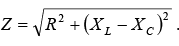 The circuit is at resonance when the inductive reactance XL is equal to the capacitive reactance XC (figure b shown below).
 Series resonance for RLC circuit at resonant frequency fr
At resonance XL = XC Then at resonance,
 where fr = resonance frequency, Hz; L = inductance, H; C = capacitance, F For any LC product [equation (1)] there is only one resonant frequency. Thus, various combinations of L and C may be used to achieve resonance if the LC product remains the same. Equation (1) may be solved for L or C to find the inductance or capacitance needed to from a series resonant circuit at a given frequency.
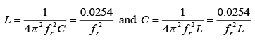 Since XL = XC, XL – XC = 0 so that
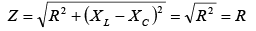 Since the impedance at resonance Z equals the resistance R, the impedance is a minimum. With minimum impedance, the circuit has maximum current determined by I = V/R. The resonant circuit has a phase angle equal to 0º so that the power factor is unity.
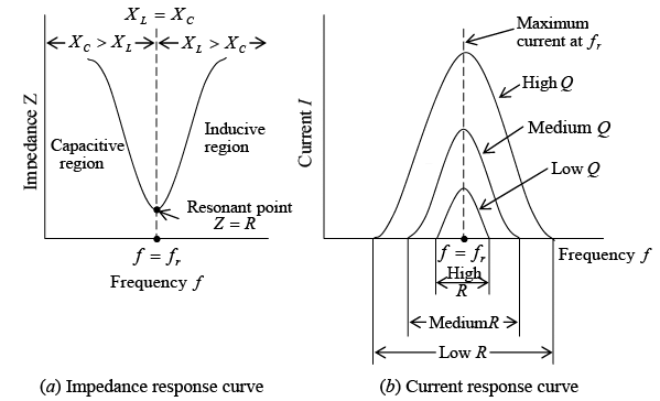 Characteristics of series RLC circuit at resonanceAt frequencies below the resonant frequency (figure a shown above). XC is greater than XL so the circuit consists of resistance and capacitive reactance. However, at frequencies above the resonant frequency, XL is greater than XC so that circuit consists of resistance and inductive reactance. At resonance, maximum current is produced for different values of resistance (figure b shown above). With a low resistance, maximum current increases sharply toward and decreases sharply from its maximum current as the circuit is tuned to and away from the resonant frequency. This condition where the curve is narrow at the resonant frequency provides good selectivity. With an increase of resistance, the curve broadens so that selectivity is less.
➤ Q of Series Circuit
The degree to which a series-tuned circuit is selective is proportional to the ratio of its inductive reactance to its resistance. This ratio XL/R is known as the Q of the circuit and is expressed as follows: Q = XL/R
where Q = quality factor or figure of merit
XL = inductive reactance, Ω
R = resistance, Ω
The lower the resistance, the higher the value of Q, the higher the Q the sharper and more selective is the resonant curve. Q has the same value if calculated with XC instead of XL since they are equal at resonance. Q = 150 is a high Q. Typical values are 50 to 250. Less than 10 is a low Q; more than 300 is a very high Q.
The Q of the circuit of the circuit is generally considered in terms of XL since the coil has the series resistance of the circuit. In this case, the Q of the coil and the Q of the series resonant circuit are the same. If extra resistance is added, the Q of the circuit will be less than the Q of the coil. The highest possible Q for the circuit is the Q of the coil. The Q of the resonant circuit can be considered a magnification factor that determines how much the voltage across L or C is increased by the resonant rise of current in a series circuit.
VL = VC = QVT
➤ Parallel Resonance
- Pure Parallel LC circuit
In the pure LC parallel-tuned circuit (that is, one in which there is no resistance), the coil and capacitor are placed in parallel and the applied voltage VT appears across these circuit components (figure shown below). In this parallel-tuned circuit, as in the series-tuned circuit, resonance occurs when the inductive reactance is equal to the capacitive reactance.
XL = XC
Because the applied voltage is common to both branches,
VL = VC
So that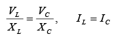 The current in the inductive branch IL equals the current in the capacitive branch IC.
IL lags the applied voltage VT by 90°, while IC leads the voltage by 90° (figure b shown below). Since the phasor currents IL and IC are equal and out of phase by 180°, their vector sum is zero so that the total current IT is zero. Under this condition the impedance of the circuit at the resonant frequency must be infinite in value.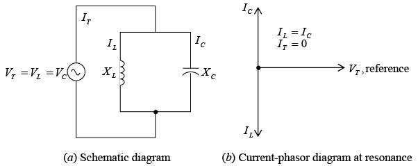 Pure LC parallel circuit
The formula for the resonant frequency of a pure LC parallel-tuned circuit is the same as that for a series circuit.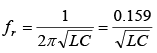 If the resonant frequency is known, then the inductance or capacitance for a parallel resonant LC circuit can be found by formulas.
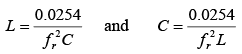
- Practical Parallel LC Circuit
In a practical LC parallel-tuned circuit (figure a shown below), there is some resistance, most of which is due to the resistance of the inductor wire. The resonant frequency of a parallel circuit also is defined as that frequency at which the parallel circuit acts as a pure resistance. Therefore, the line current IT must be in phase with the applied voltage VT (unity power factor) (figure b shown below). This means that the out-of-phase or quadrature component of the current through the inductive branch IL must be equal to the current through the capacitive branch IC; and the total line current IT equals the in-phase component of the current through the inductive branch, or IT = Ir (figure b shown below). Since the impedance is maximum, IT is minimum. Practical parallel LC circuit
The resonant frequency for the circuit (figure a shown above) is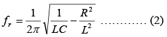 where fr = resonant frequency, Hz; L = inductance, H; C = capacitance, F; R = resistance, Ω .
If the Q of the coil is high, say greater than 10, or the term 1/LC >> R2/L2, then, for practical purposes, the term R2/L2 can be disregarded. The result is that equation (2) becomes equation (1), the resonant frequency formula for series resonance.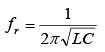 the total impedance at resonance of the practical LC parallel circuit is
 In terms of quality factor Q, ZT at resonance can also be found by
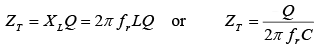 The impedance ZT of a practical parallel circuit is maximum at the resonant frequency and decreases at frequencies below and above the resonant frequency (figure a shown below). An increase in resistance decreases the impedance and causes the impedance to vary less “sharply” as the circuit is tuned over a band of frequencies below and above the resonant frequency (figure b shown below). At frequencies below resonance, XC > XL and IL > IC so that the parallel-tuned circuit is inductive (figure a and c shown below). At frequencies above resonance, the reverse condition is true, XL > XC and IC > IL, so that now the circuit is capacitive (figure a and c shown below c). Since the impedance ZT is maximum at parallel resonance, IT is minimum (figure c shown below).
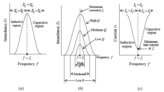 Impedance and current response curves of practical parallel LC circuit at resonance
 - Q of Parallel Circuit
For a parallel resonant circuit in which R is very low compared with XL,
Q = XL/R.
where R is the resistance of the coil in series with XL . If the resistance of the source supply is very high and there is no other resistance branch shunting the tuned circuit, the Q of the parallel resonant circuit is the same as the Q of the coil.
➤ Bandwidth and Power of Resonant Circuit
The width of the resonant band of frequencies centered around fr is called the bandwidth of the tuned circuit. In figure a shown below, the group of frequencies with a response of 70.7 percent of maximum or more is considered the bandwidth of the tuned circuit. For a series resonant circuit, the bandwidth is measured between the two frequencies f1 and f2 producing 70.7 percent of the maximum current at fr (figure b shown below). For a parallel resonant circuit, the bandwidth is measured between the two frequencies, allowing 70.7 percent of the maximum total impedance at fr (figure c shown below).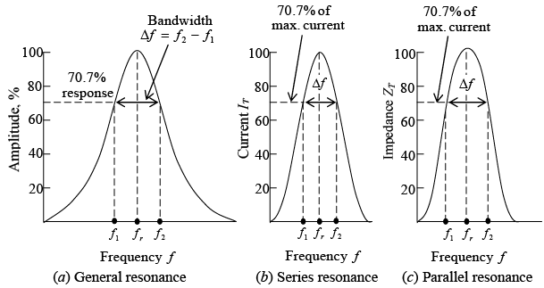 Bandwidth of a tuned LC circuitAt each frequency f1 and f2 the net capacitive or net inductive reactance equals the resistance. Then ZT of the series RLC resonant circuit is √2 or 1.4 times greater than R. The current then is I/√2 = 0.707 I. Since power is I2R or V2/R and (0.707)2 = 0.50, the bandwidth at 70.7 percent response in current or voltage is also the bandwidth of half power points.
Bandwidth (BW) in terms of Q is High Q means narrow bandwidth, whereas low Q yields greater bandwidth. Either f1 or f2 is separated from fr by one-half of the total bandwidth, so these edge frequencies can be calculated.
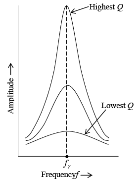 Resonant response curves: higher Q provides sharper resonance, lower Q provides broader responseTable: Comparison of Series and Parallel Resonance
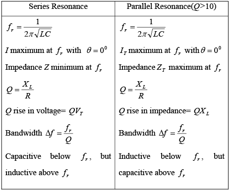
|
82 videos|32 docs|22 tests
|
FAQs on Single Phase Circuits - Electricity & Magnetism - Physics
| 1. What are the advantages of single phase circuits? |  |
| 2. What is the difference between single phase and three phase circuits? | |
| 3. How does a single phase circuit work? | |
| 4. What are the common applications of single phase circuits? | |
| 5. What are the limitations of single phase circuits? | |


practice quizzes
,video lectures
,shortcuts and tricks
,MCQs
,Objective type Questions
,Single Phase Circuits | Electricity & Magnetism - Physics
,Single Phase Circuits | Electricity & Magnetism - Physics
,Exam
,Extra Questions
,Semester Notes
,mock tests for examination
,ppt
,Important questions
,Previous Year Questions with Solutions
,Single Phase Circuits | Electricity & Magnetism - Physics
,study material
,past year papers
,Free
,Viva Questions
,Sample Paper
,Summary
;


Single Phase Circuits Free PDF Download
Importance of Single Phase Circuits
Single Phase Circuits Notes
Single Phase Circuits Physics Questions
Study Single Phase Circuits on the App
|
© EduRev
|
Education Revolution
|


|


within 7 days!