Short Notes: Principle of Energy Conversion | Electrical Machines - Electrical Engineering (EE) PDF Download
Introduction
- A device which converts electrical energy into mechanical energy or mechanical energy into electrical energy is known as electromechanical energy conversion device.

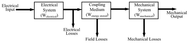
- The electromechanical energy conversion takes place through the medium of a magnetic field. The magnetic field is used as a coupling medium between electrical and mechanical systems. It is because the energy storing capacity of a magnetic field is very high.

Therefore, an electromechanical energy converter has three main parts −
- Mechanical system
- Coupling medium
- Electrical system
The electromechanical energy converters are of two types −
- Gross-motion devices − Such as electrical motors or generators.
- Incremental motion devices − Such as microphones, loudspeakers, electromagnetic relays and electrical measuring instruments, etc.
When the electromechanical energy conversion takes place from electrical energy to mechanical energy, the converter is known as motor. Whereas, when the conversion takes place from mechanical energy to electrical energy, the device is known as generator.
In the electrical machines, conversion of energy from electrical to mechanical or from mechanical to electrical results following two electromagnetic phenomena −
- When a conductor moves in a magnetic field, an EMF is induced in the conductor.
- When a current carrying conductor is placed in a magnetic field, a mechanical force acts on the conductor.
These two effects occur simultaneously whenever energy conversion takes place from electrical to mechanical or vice-versa.
In motoring action, electric current flows through the conductors placed in a magnetic field due to which a force is produced on each conductor. The conductors are placed on a rotor, which is free to move. Therefore, an electromagnetic torque is produced on the rotor so that the rotor starts rotating at some speed.
The torque produced on the rotor is transferred to a shaft of the rotor and hence it can drive a mechanical load. Since the conductors are rotating in a magnetic field, thus an EMF is also induced in each conductor.
In generating action, in this case the rotor is driven by a prime mover. An EMF is induced in the rotor conductors due to which a current will flow and deliver electric power to the load. In addition to this, the current flowing through the conductors will interact with the magnetic field to produce a reaction torque, which will tend to oppose the torque developed by the prime mover.

Principle of Conservation of Energy
- The principle of conservation of energy states that “the energy can neither be create not destroyed. It can only be converted from one form to another”.
- In an electromechanical energy conversion device, the total input energy is equal to the sum of following three components −
- Energy dissipated,
- Energy stored, and
- Useful output energy.
- Hence, the principle of electromechanical energy conversion is based on the following two equations −
- The energy balance equation or energy transfer equation for motoring action can be written as −
[Electrical energy input] = [Energy disipated in electrical losses] + [Energy stored in coupling medium] + [Mechanical energy output] - The energy balance equation or energy transfer equation for generating action can be written as −
[Mechanical energy input] = [Electrical Energy Output] + [Energy stored in coupling medium] + [Energy disipated]
|
19 videos|90 docs|25 tests
|

|
4.88/5 Rating |

|
Dec 22, 2024 Last updated |

|
Explore Courses for Electrical Engineering (EE) exam
|
|
Previous Year Questions with Solutions
,video lectures
,Sample Paper
,Viva Questions
,Short Notes: Principle of Energy Conversion | Electrical Machines - Electrical Engineering (EE)
,Short Notes: Principle of Energy Conversion | Electrical Machines - Electrical Engineering (EE)
,ppt
,Extra Questions
,shortcuts and tricks
,practice quizzes
,study material
,Exam
,Semester Notes
,MCQs
,Objective type Questions
,Short Notes: Principle of Energy Conversion | Electrical Machines - Electrical Engineering (EE)
,past year papers
,Important questions
,Summary
,mock tests for examination
,Free
;


Short Notes: Principle of Energy Conversion Free PDF Download
Importance of Short Notes: Principle of Energy Conversion
Short Notes: Principle of Energy Conversion
Short Notes: Principle of Energy Conversion Electrical Engineering (EE) Questions
Study Short Notes: Principle of Energy Conversion on the App
|
© EduRev
|
Education Revolution
|


|


