Overhead Insulators & Underground Cables - 1 | Power Systems - Electrical Engineering (EE) PDF Download
Electrical Insulator
- Electrical Insulator must be used in electrical system to prevent unwanted flow of current to the earth from its supporting points. The insulator plays a vital role in electrical system. Electrical Insulator is a very high resistive path through which practically no current can flow. In transmission and distribution system, the overhead conductors are generally supported by supporting towers or poles.
- The towers and poles both are properly grounded. So there must be insulator between tower or pole body and current carrying conductors to prevent the flow of current from conductor to earth through the grounded supporting towers or poles.
Insulating Material
- The main cause of failure of overhead line insulator, is flash over, occurs in between line and earth during abnormal over voltage in the system. During this flash over, the huge heat produced by arcing, causes puncher in insulator body. Viewing this phenomenon the materials used for electrical insulator, has to posses some specific properties.
Properties of Insulating Material
The materials generally used for insulating purpose is called insulating material. For successful utilization,
this material should have some specific properties as listed below.
- It must be mechanically strong enough to carry tension and weight of conductors.
- It must have very high dielectric strength to withstand the voltage stresses in High Voltage system.
- It must possesses high Insulation Resistance to prevent leakage current to the earth.
- The insulating material must be free from unwanted impurities.
- It should not be porous.
- There must not be any entrance on the surface of electrical insulator so that the moisture or gases can enter in it.
- There physical as well as electrical properties must be less affected by changing temperature.
There are mainly three types of insulator used as overhead insulator likewise
- Pin Insulator
- Suspension Insulator
- Strain Insulator
In addition to that there are other two types of electrical insulator available mainly for low voltage application i.e. Stray Insulator and Shackle Insulator.
Pin Insulator
- Pin Insulator is earliest developed overhead insulator, but still popularly used in power network up to 33KV system. Pin type insulator can be one part, two parts or three parts type, depending upon application voltage. In 11KV system we generally use one part type insulator where whole pin insulator is one piece of properly shaped porcelain or glass. As the leakage path of insulator is through its surface, it is desirable to increase the vertical length of the insulator surface area for lengthening leakage path.
- In order to obtain lengthy leakage path, one, tower or more rain sheds or petticoats are provided on the insulator body. In addition to that rain shed or petticoats on an insulator serve another purpose. These rain sheds or petticoats are so designed, that during raining the outer surface of the rain shed becomes wet but the inner surface remains dry and non-conductive. So there will be discontinuations of conducting path through the wet pin insulator surface.
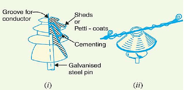
- In higher voltage like 33KV and 66KV manufacturing of one part porcelain pin insulator becomes difficult. Because in higher voltage, the thickness of the insulator become more and a quite thick single piece porcelain insulator cannot manufactured practically. In this case we use multiple part pin insulator, where a number of properly designed porcelain shells are fixed together by Portland cement to form one complete insulator unit. For 33KV tow parts and for 66KV three parts pin insulator are generally used.
Designing Consideration of Electrical Insulator:
- The live conductor attached to the top of the pin insulator is at a potential and bottom of the insulator fixed to supporting structure of earth potential. The insulator has to withstand the potential stresses between conductor and earth. The shortest distance between conductor and earth, surrounding the insulator body, along which electrical discharge may take place through air, is known as flash over distance.
- When insulator is wet, its outer surface becomes almost conducting. Hence the flash over distance of insulator is decreased. The design of an electrical insulator should be such that the decrease of flash over distance is minimum when the insulator is wet. That is why the upper most petticoat of a pin insulator has umbrella type designed so that it can protect, the rest lower part of the insulator from rain. The upper surface of top most petticoat is inclined as less as possible to maintain maximum flash over voltage during raining.
- To keep the inner side of the insulator dry, the rain sheds are made in order that these rain sheds should not disturb the voltage distribution they are so designed that their subsurface at right angle to the electromagnetic lines of force.
Post insulator
Post insulator is more or less similar to Pin insulator, but former is suitable for higher voltage application. Post insulator has higher numbers of petticoats and has greater height. We can mount this type of insulator on supporting structure horizontally as well as vertically. The insulator is made of one piece of porcelain and it has clamp arrangement are in both top and bottom end for fixing. The main differences between pin insulator and post insulator are,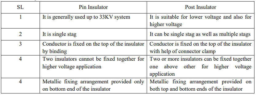
Suspension Insulator
- In higher voltage, beyond 33KV, it becomes uneconomical to use pin insulator because size, weight of the insulator become more. Handling and replacing bigger size single unit insulator are quite difficult task. For overcoming these difficulties, suspension insulator was developed. In suspension insulator numbers of insulators are connected in series to form a string and the line conductor is carried by the bottom most insulator. Each insulator of a suspension string is called disc insulator because of their disc like shape.
Advantages of Suspension Insulator:
- Suspension type insulators are cheaper than pin type insulators for voltages beyond 33 kV.
- Each unit or disc of suspension type insulator is designed for low voltage, usually 11 kV. Depending upon the working voltage, the desired number of discs can be connected in series.
- If anyone disc is damaged, the whole string does not become useless because the damaged disc can be replaced by the sound one.
- The suspension arrangement provides greater flexibility to the line. The connection at the cross arm is such that insulator string is free to swing in any direction and can take up the position where mechanical stresses are minimum.
- In case of increased demand on the transmission line, it is found more satisfactory to supply. the greater demand by raising the line voltage than to provide another set of conductors. The additional insulation required for the raised voltage can be easily obtained in the suspension arrangement by adding the desired number of discs.
- The suspension type insulators are generally used with steel towers. As the conductors run below the earthed cross-arm of the tower, therefore, this arrangement provides partial protection from lightning.
Disadvantages of Suspension Insulator:
- Suspension insulator string costlier than pin and post type insulator.
- Suspension string requires more height of supporting structure than that for pin or post insulator to maintain same ground clearance of current conductor.
- The amplitude of free swing of conductors is larger in suspension insulator system, hence, more spacing between conductors should be provided.
Strain Insulator
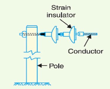
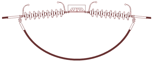
- When suspension string is used to sustain extraordinary tensile load of conductor it is referred as string insulator. When there is a dead end or there is a sharp corner in transmission line, the line has to sustain a great tensile load of conductor or strain. A strain insulator must have considerable mechanical strength as well as the necessary electrical insulating properties.
- When suspension string is used to sustain extraordinary tensile load of conductor it is referred as string insulator. When there is a dead end or there is a sharp corner in transmission line, the line has to sustain a great tensile load of conductor or strain. A strain insulator must have considerable mechanical strength as well as the necessary electrical insulating properties.

Stay insulator
 For low voltage lines, the stays are to be insulated from ground at a height. The insulator used in the stay wire is called as the stay insulator and is usually of porcelain and is so designed that in case of breakage of the insulator the guy-wire will not fall to the ground.
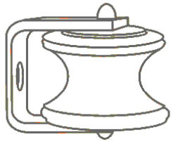
Shackle insulator or spool insulator
- The shackle insulator or spool insulator is usually used in low voltage distribution network. It can be used both in horizontal and vertical position. The use of such insulator has decreased recently after increasing the using of underground cable for distribution purpose. The tapered hole of the spool insulator distributes the load more evenly and minimizes the possibility of breakage when heavily loaded. The conductor in the groove of shackle insulator is fixed with the help of soft binding wire.
Potential Distribution over a string of Suspension Insulator
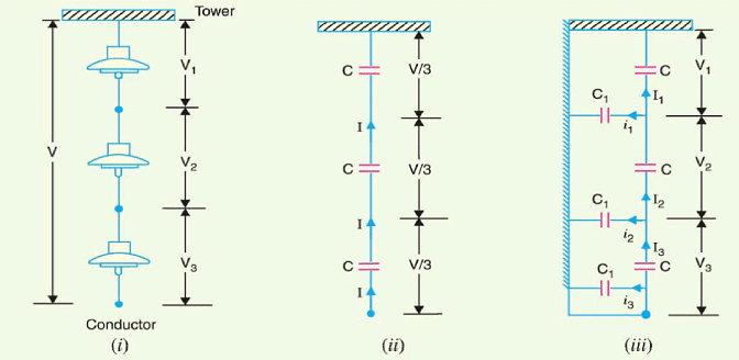
- A string of suspension insulators consists of a number of porcelain discs connected in series through metallic links. Fig. 2.3(i) shows 3-disc string of suspension insulators. The porcelain portion of each disc is in between two metal links. Therefore, each disc forms a capacitor C as shown in Fig.2.3(ii). This is known as mutual capacitance or self-capacitance.
- If there were mutual capacitance alone, then charging current would have been the same through all the discs and consequently voltage across each unit would have been the same i.e., V/3 as shown in Fig. 2.3(ii). However, in actual practice, capacitance also exists between metal fitting of each disc and tower or earth. This is known as shunt capacitance C1. Due to shunt capacitance, charging current is not the same through all the discs of the string [See Fig2.3(iii)]. Therefore, voltage across each disc will be different.
- Obviously, the disc nearest to the line conductor will have the maximum voltage. Thus referring to Fig 2.3(iii), V3 will be much more than V2 or V1.
The following points may be noted regarding the potential distribution over a string of suspension insulators:
- The voltage impressed on a string of suspension insulators does not distribute itself uniformly
- across the individual discs due to the presence of shunt capacitance.
- The disc nearest to the conductor has maximum voltage across it. As we move towards the crossarm, the voltage across each disc goes on decreasing.
- The unit nearest to the conductor is under maximum electrical stress and is likely to be punctured.
- Therefore, means must be provided to equalize the potential across each unit.
- The presence of stray capacitance causes unequal potential distribution over the string. The end unit of the string (which is the closest to the line) takes maximum potential difference and the upper units have a gradually decreased potential difference until the uppermost unit which\ has the lowest potential difference. The next proof illustrates this concept.
Suspension Insulator string
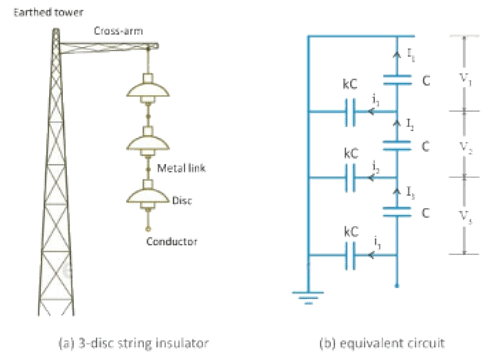
If there were only mutual capacitances, then the charging current would have been the same through all the discs. In this case, the voltage would have been uniformly distributed across the string, i.e. voltage across each disc would have been the same. But, due to the shut capacitances, charging current is not the same through all the discs.
From the above equivalent circuit, applying Kirchoff's current law to node A,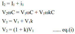
applying Kirchoff's current law to node B,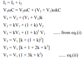
Now, voltage between the conductor and the earther tower is,
from the above equations (i), (ii) & (iii), it is clear that the voltage across the top disc is minimum while voltage across the disc nearest to the conductor is maximum, i.e. V3 = V1 (1 + 3k + k2). As we move towards the cross arm, voltage across the disc goes on decreasing. Due to this non-uniform voltage distribution across the string, the unit nearest to the conductor is under maximum electrical stress and is likely to be punctured.
String Efficiency
- As explained above, voltage is not uniformly distributed over a suspension insulator string. The disc nearest to the conductor has maximum voltage across it and, hence, it will be under maximum electrical stress. Due to this, the disc nearest to the conductor is likely to be punctured and subsequently, other discs may puncture successively. Therefore, this unequal voltage distribution is undesirable and usually expressed in terms of string efficiency. The ratio of voltage across the whole string to the product of number of discs and the voltage across the disc nearest to the conductor is called as string efficiency
String efficiency = Voltage across the string / (number of discs X voltage across the disc nearest to the conductor). - Greater the string efficiency, more uniform is the voltage distribution. String efficiency becomes 100% if the voltage across each disc is exactly the same, but this is an ideal case and impossible in practical scenario. However, for DC voltages, insulator capacitances are ineffective and voltage across each unit would be the same. This is why string efficiency for DC system is 100%. Inequality in voltage distribution increases with the increase in the number of discs in a string. Therefore, shorter strings are more efficient than longer string insulators.
Methods of Improving String Efficiency
Using Longer Cross Arms:
- It is clear from the above mathematical expression of string efficiency that the value of string efficiency depends upon the value of k. Lesser the value of k, the greater is the string efficiency. As the value of k approaches to zero, the string efficiency approaches to 100%. The value of k can be decreased by reducing the shunt capacitance. In order to decrease the shunt capacitance, the distance between the insulator string and the tower should be increased, i.e. longer cross-arms should be used. However, there is a limit in increasing the length of cross-arms due to economic considerations.
Grading Of Insulator Discs:
- In this method, voltage across each disc can be equailized by using discs with different capacitances. For equalizing the voltage distribution, the top unit of the string must have minimum capacitance, while the disc nearest to the conductor must have maximum capacitance. The insulator discs of different dimensions are so chosen that the each disc has a different capacitance. They are arranged in such a way that the capacitance increases progressively towards the bottom. As voltage is inversely proportional to capacitance, this method tends to equalize the voltage distribution across each disc.
By Using A Guard Or Grading Ring:
- A guard ring or grading ring is basically a metal ring which is electrically connected to the conductor surrounding the bottom unit of the string insulator. The guard ring introduces capacitance between metal links and the line conductor which tends to cancel out the shunt capacitances. As a result, nearly same charging current flows through each disc and, hence, improving the string efficiecy. Grading rings are sometimes similar to corona rings, but they encircle insulators rather than conductors.
Underground Cables
- Electric power can be transmitted or dis tributed either by overhead system or by underground cables. The underground cables have serveral advantages such as less liable to damage through storms or lightning, low maintenance cost, less chances of faults, smaller voltage drop and better general appearance. However, their major drawback is that they have greater installation cost and introduce insulation problems at high voltages compared with the equivalent overhead system. For this reason, underground cables are employed where it is impracticable to use overhead lines. Such locations may be thickly populated areas where municipal authorities prohibit overhead lines for reasons of safety, or around plants and substations or where maintenance conditions do not permit the use of overhead construction.
- The chief use of underground cables for many years has been for distribution of electric power in congested urban areas at comparatively low or moderate voltages. However, recent improve- ments in the design and manufacture have led to the development of cablessuitable for use at high voltages. This has made it possible to employ underground cables for transmission of electric power for short or moderate distances. In this chapter, we shall focus our attention on the various aspects of underground cables and their increasing use in power system.
- An underground cable essentially consists of one or more conductors covered with suitable insula- tion and surrounded by a protecting cover. Although several types of cables are available, the type of cable to be used will depend upon the working voltage and service requirements. In general, a cable must fulfil the following necessary requirements :
- The conductor used in cables should be tinned stranded copper or aluminium of high conductivity. Stranding is done so that conductor may become flexible and carry more current.
- The conductor size should be such that the cable carries the desired load current without overheating and causes voltage drop within permissible limits.
- The cable must have proper thickness of insulation in order to give high degree of safety and reliability at the voltage for which it is designed.
- The cable must be provided with suitable mechanical protection so that it may withstand the rough use in laying it.
- The materials used in the manufacture of cables should be such that there is complete chemical and physical stability throughout.
Construction of cables
Figure shows the general construction of a 3-conductor cable. The various parts are :
- Cores or Conductors. A cable may have one or more than one core (conductor) depending upon the type of service for which it is intended. For instance, the 3-conductor cable shown in Figure is used for 3-phase service. The conductors are made of tinned copper or aluminium and are usually stranded in order to provide flexibility to the cable.
- Insulation. Each core or conductor is provided with a suitable thickness of insulation, the thickness of layer depending upon the voltage to be withstood by the cable. The commonly used materials for insulation are impregnated paper, varnished cambric or rubber mineral compound.
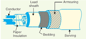
- Metallic sheath. In order to protect the cable from moisture, gases or other damaging liquids
(acids or alkalis) in the soil and atmosphere, a metallic sheath of lead or aluminium is provided over the insulation as shown in Figure
Bedding. Over the metallic sheath is applied a layer of bedding which consists of a fibrous material like jute or hessian tape. The purpose of bedding is to protect the metallic sheath against corrosion and from mechanical injury due to armouring.
Armouring. Over the bedding, armouring is provided which consists of one or two layers of
galvanized steel wire orsteel tape. Its purpose isto protect the cable from mechanical injury while laying it and during the course of handling. Armouring may not be done in the case of some cables.
Serving. In order to protect armouring from atmospheric conditions, a layer of fibrous
material (like jute) similar to bedding is provided over the armouring. This is known as serving.
It may not be out of place to mention here that bedding, armouring and serving are only applied to the cables for the protection of conductor insulation and to protect the metallic sheath from mechanical injury.
Insulating materials for cables
The satisfactory operation of a cable depends to a great extent upon the characteristics of insulation used. Therefore, the proper choice of insulating material for cables is of considerable importance. In general, the insulating materials used in cables should have the following properties:
- High insulation resistance to avoid leakagecurrent.
- High dielectric strength to avoid electrical breakdown of thecable.
- Highmechanicalstrength to withstand the mechanical handling of cables.
- Non-hygroscopic i.e., it should not absorb moisture from air or soil. The moisture tends to decrease the insulation resistance and hastens the breakdown of the cable. In case the insulating material is hygroscopic, it must be enclosed in a waterproof covering like lead sheath.
- Non-inflammable.
- Low cost so as to make the underground system a viable proposition.
- Unaffected by acids and alkalis to avoid any chemical action.
No one insulating material possesses all the above mentioned properties. Therefore, the type of
insulating material to be used depends upon the purpose for which the cable is required and the quality of insulation to be aimed at. The principal insulating materials used in cables are rubber, vulcanized India rubber, impregnated paper, varnished cambric and polyvinylchloride.
- Rubber. Rubber may be obtained from milky sap of tropical trees or it may be produced from oil products. It has relative permittivity varying between 2 and 3, dielectric strength is about 30 kV/mm and resistivity of insulation is 1017 cm. Although pure rubber has reasonably high insulating properties, it suffers from some major drawbacks viz., readily absorbs moisture, maximum safe temperature is low (about 38ºC), soft and liable to damage due to rough handling and ages when exposed to light. Therefore, pure rubber cannot be used as an insulating material.
- Vulcanized India Rubber (V.I.R.). It is prepared by mixing pure rubber with mineral mat- ter such as zine oxide, red lead etc., and 3 to 5% of sulphur. The compound so formed is rolled into thin sheets and cut into strips. The rubber compound is then applied to the conductor and is heated to a temperature of about 150ºC. The whole process is called vulcanization and the product obtained is known as vulcanized India rubber.
- Vulcanized India rubber has greater mechanical strength, durability and wear resistant
property than pure rubber. Its main drawback is that sulphur reacts very quickly with copper and for this reason, cables using VIR insulation have tinned copper conductor. The VIR insulation is generally used for low and moderate voltage cables - Impregnated paper. It consists of chemically pulped paper made from wood chippings and
impregnated with some compound such as paraffinic or naphthenic material. This type of insulation has almost superseded the rubber insulation. It is because it has the advantages of low cost, low capacitance, high dielectric strength and high insulation resistance. The only disadvantage is that paper is hygroscopic and even if it is impregnated with suitable compound, it absorbs moisture and thus lowers the insulation resistance of the cable. For this reason, paper insulated cables are always provided with some protective covering and are never left unsealed. If it is required to be left unused on the site during laying, its ends are temporarily covered with wax or tar. Since the paper insulated cables have the tendency to absorb moisture, they are used where the cable route has a *few joints. For instance, they can be profitably used for distribution at low voltages in congested areas where the joints are generally provided only at the terminal apparatus. However, for smaller installations, where the lengths are small and joints are required at a number of places, VIR cables will be cheaper and durable than paper insulated cables.
Varnished cambric. It is a cotton cloth impregnated and coated with varnish. This type of insulation is also known as empire tape. The cambric is lapped on to the conductor in the form of a tape and its surfaces are coated with petroleum jelly compound to allow for the sliding of one turn over another as the cable is bent. As the varnished cambric is hygroscopic, therefore, such cables are always provided with metallic sheath. Its dielectric strength is about 4 kV/mm and permittivity is 2.5 to 3.8.
Polyvinyl chloride (PVC). This insulating material is a synthetic compound. It is obtained from the polymerization of acetylene and is in the form of white powder. For obtaining this material as a cable insulation, it is compounded with certain materials known as plasticizers which are liquids with high boiling point. The plasticizer forms a gel and renders the material plastic over the desired range of temperature. Polyvinyl chloride has high insulation resistance, good dielectric strength and mechanical tough- ness over a wide range of temperatures. It is inert to oxygen and almost inert to many alkalis and acids. Therefore, this type of insulation is preferred over VIR in extreme environmental conditions such as in cement factory or chemical factory. As the mechanical properties (i.e., elasticity etc.) of PVC are not so good as those of rubber, therefore, PVC insulated cables are generally used for low and medium domestic lights and power installations.
|
21 videos|109 docs|45 tests
|


