Detailed Notes: Signal Phase Rectifier | Power Electronics - Electrical Engineering (EE) PDF Download
Introduction
- Rectification converts an oscillating sinusoidal AC voltage source into a constant current DC voltage supply by means of diodes, thyristors, transistors, or converters. This rectifying process can take on many forms with half-wave, full-wave, uncontrolled and fully-controlled rectifiers transforming a single-phase or three-phase supply into a constant DC level. In this tutorial we will look at single-phase rectification and all its forms.
- Rectifiers are one of the basic building blocks of AC power conversion with half-wave or full-wave rectification generally performed by semiconductor diodes. Diodes allow alternating currents to flow through them in the forward direction while blocking current flow in the reverse direction creating a fixed DC voltage level making them ideal for rectification.
- However, direct current which has been rectified by diodes is not as pure as that obtained from say, a battery source, but has voltage changes in the form of ripples superimposed on it as a result of the alternating supply.
- But for single phase rectification to take place, we need an AC sinusoidal waveform of a fixed voltage and frequency as shown.
AC Sinusoidal Waveform

- AC waveforms generally have two numbers associated with them. The first number expresses the degree of rotation of the waveform along the x-axis by which the alternator has rotated from 0-to-360o. This value is known as the period (T) which is defined as the interval taken to complete one full cycle of the waveform.
- Periods are measured in units of degrees, time, or radians. The relationship between a sine waves periods and frequency is defined as: T = 1/ƒ.
- The second number indicates the amplitude of the value, either current or voltage, along the y-axis. This number gives the instantaneous value from zero to some peak or maximum value ( AMAX, VMAX or IMAX ) indicating the sine waves greatest amplitude before returning back to zero again. For a sinusoidal waveform there are two maximum or peak values, one for the positive and one for the negative half-cycles.
- But as well as these two values, there are two more which are of interest to us for rectification purposes. One is the sinusoidal waveforms Average Value and the other is its RMS Value. The average value of a waveform is obtained by adding the instantaneous values of voltage (or current) over one half-cycle and is found as: 0.6365*VP.
- Note that the average value over one complete cycle of a symmetrical sine wave will be zero as the average positive half-wave is cancelled by the opposite average negative half-wave. That is +1 + (-1) = 0.
- The RMS, root mean squared or effective value of a sinusoid (a sinusoid is another name for a sine wave) delivers the same amount of energy to a resistance as does a DC supply of the same value. The root mean square (rms) value of a sinusoidal voltage (or current) is defined as: 0.7071*VP.
Single Phase Rectifier
- All single phase rectifiers use solid state devices as their primary AC-to-DC converting device. Single phase uncontrolled half-wave rectifiers are the simplest and possibly the most widely used rectification circuit for small power levels as their output is heavily affected by the reactance of the connected load.
- For uncontrolled rectifier circuits, semiconductor diodes are the most commonly used device and are so arranged to create either a half-wave or a full-wave rectifier circuit. The advantage of using diodes as the rectification device is that by design they are unidirectional devices having an inbuilt one-way pn-junction.
- This pn-junction converts the bi-directional alternating supply into a one-way unidirectional current by eliminating one-half of the supply. Depending upon the connection of the diode, it could for example pass the positive half of the AC waveform when forward-biased, while eliminating the negative half-cycle when the diode becomes reverse-biased.
- The reverse is also true by eliminate the positive half or the waveform and passing the negative half. Either way, the output from a single diode rectifier consists of only one half of the 360o waveform as shown.
Half-wave Rectification

- The single-phase half-wave rectifier configuration above passes the positive half of the AC supply waveform with the negative half being eliminated. By reversing the direction of the diode we can pass negative halves and eliminate the positive halves of the AC waveform. Therefore the output will be a series of positive or negative pulses.
- Thus there is no voltage or current applied to the connected load, RL for half of each cycle. In other words, the voltage across the load resistance, RL consists of only half waveforms, either positive or negative, as it operates during only one-half of the input cycle, hence the name of half-wave rectifier.
- Hopefully we can see that the diode allows current to flow in one direction only producing an output which consists of half-cycles. This pulsating output waveform not only varies ON and OFF every cycle, but is only present 50% of the time and with a purely resistive load, this high voltage and current ripple content is at its maximum.
- This pulsating DC means that the equivalent DC value dropped across the load resistor, RL is therefore only one half of the sinusoidal waveforms value. Since the maximum value of the waveforms sine function is 1 ( sin(90o) ), the Average or Mean DC value taken over one-half of a sinusoid is defined as: 0.637 x maximum amplitude value.
- So during the positive half-cycle, AAVE equals 0.637*AMAX. However as the negative half-cycles are removed due to rectification by the reverse biased diode, the average value of the waveform during this negative half-cycle will be zero as shown.
Sinusoids Average Value

- So for a half-wave rectifier, 50% of the time there is an average value of 0.637*AMAX and 50% of the time there is zero. If the maximum amplitude is 1, the average or DC value equivalent seen across the load resistance, RL will be:

- Thus the corresponding expressions for the average value of voltage or current for a half-wave rectifier with pulsating DC is given as:
VAVE = 0.318*VMAX
IAVE = 0.318*IMAX - Note that the maximum value, AMAX is that of the input waveform, but we could also use its RMS, or “root mean squared” value to find the equivalent DC output value of a single phase half-wave rectifier.
- To determine the average voltage for a half-wave rectifier, we multiply the RMS value by 0.9 (form factor) and divide the product by 2, that is multiplying it by 0.45 giving:
VAVE = 0.45*VRMS
IAVE = 0.45*IRMS - Then we can see that a half-wave rectifier circuit converts either the positive or negative halves of an AC waveform, depending on the diodes direction, into a pulsed DC output which has an equivalent DC value of 0.318*AMAX or 0.45*ARMS as shown.
Half-wave Rectifier Average Voltage
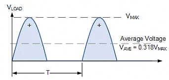
Rectification Example
- A single phase half-wave rectifier is connected to a 50V RMS 50Hz AC supply. If the rectifier is used to supply a resistive load of 150 Ohms. Calculate the equivalent DC voltage developed across the load, the load current and power dissipated by the load. Assume ideal diode characteristics.
- First we need to convert the 50 volts RMS to its peak or maximum voltage equivalent (its not necessary but it helps).
(a) Maximum Voltage Amplitude, VM
- VM = 1.414*VRMS = 1.414*50 = 70.7 volts
(b) Equivalent DC Voltage, VDC
- VDC = 0.318*VM = 0.318*70.7 = 22.5 volts
(c) Load Current, IL
- IL = VDC ÷ RL = 22.5/150 = 0.15A or 150mA
(d) Power Dissipated by the Load, PL
- PL = V*I or I2*RL = 22.5*0.15 = 3.375W ≅ 3.4W
In practice, VDC would be slightly less due to the forward biased 0.7 volt voltage drop across the rectifying diode.
One of the main disadvantages of a single-phase half-wave rectifier is that there is no output during half of the available input sinusoidal waveform resulting in a low average value as we have seen. One way to overcome this is to use more diodes to produce a full-wave rectifier.
Full-wave Rectification
- Unlike the previous half-wave rectifier, the full-wave rectifier utilises both halves of the input sinusoidal waveform to provide a unidirectional output. This is because the full-wave rectifier basically consists of two half-wave rectifiers connected together to feed the load.
- The single phase full-wave rectifier does this by using four diodes arranged in a bridge arrangement passing the positive half of the waveform as before but inverting the negative half of the sine wave to create a pulsating DC output.
- Even though the the voltage and current output from the rectifier is pulsating, it does not reverse direction using the full 100% of the input waveform and thus providing full-wave rectification.
Single Phase Full-wave Bridge Rectifier

- This bridge configuration of diodes provides full-wave rectification because at any time two of the four diodes are forward biased while the other two are reverse biased. Thus there are two diodes in the conduction path instead of the single one for the half-wave rectifier.
- Therefore there will be a difference in voltage amplitude between VIN and VOUT due to the two forward voltage drops of the serially connected diodes. Here as before, for simplicity of the maths we will assume ideal diodes.
- So how does the single phase full-wave rectifier work. During the positive half cycle of VIN, diodes D1 and D4 are forward biased while diodes D2 and D3 are reverse biased.
- Then for the positive half cycle of the input waveform, current flows along the path of: D1 – A – RL – B – D4 and back to the supply.
- During the negative half cycle of VIN, diodes D3 and D2 are forward biased while diodes D4 and D1 are reverse biased.
- For the negative half cycle of the input waveform, current flows along the path of: D3 – A – RL – B – D2 and back to the supply.
- In both cases the positive and negative half-cycles of the input waveform produce positive output peaks regardless of polarity of input waveform and as such the load current, i always flows in the SAME direction through the load, RL between points or nodes A and B. Thus the negative half-cycle of the source becomes a positive half-cycle at load.
- So whichever set of diodes are conducting, node A is always more positive than node B. Therefore the load current and voltage are unidirectional or DC giving us the following output waveform.
Full-wave Rectifier Output Waveform
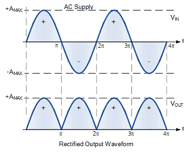
- Although this pulsating output waveform uses 100% of the input waveform, its average DC voltage (or current) is not at the same value. We remember from above that the average or mean DC value taken over one-half of a sinusoid is defined as: 0.637 x maximum amplitude value.
- However unlike half-wave rectification above, full-wave rectifiers have two positive half-cycles per input waveform giving us a different average value as shown.
Full-wave Rectifier Average Value
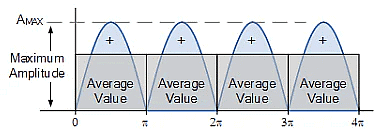
- Here we can see that for a full-wave rectifier, for each positive peak there is an average value of 0.637*AMAX and as there are two peaks per input waveform, this means there are two lots of average value summed together.
- Thus the DC output voltage of a full-wave rectifier is twice that of the previous half-wave rectifier. If the maximum amplitude is 1, the average or DC value equivalent seen across the load resistance, RL will be:

- Thus the corresponding expressions for the average value of voltage or current for a full-wave rectifier is given as:
VAVE = 0.637*VMAX
IAVE = 0.637*IMAX - As before, the maximum value, AMAX is that of the input waveform, but we could also use its RMS, or root mean squared value to find the equivalent DC output value of a single phase full-wave rectifier. To determine the average voltage for a full-wave rectifier, we multiply the RMS value by 0.9 giving:
VAVE = 0.9*VRMS
IAVE = 0.9*IRMS - Then we can see that a full-wave rectifier circuit converts BOTH the positive or negative halves of an AC waveform into a pulsed DC output that has a value of 0.637*AMAX or 0.9*ARMS as shown.
Full-wave Rectifier Average Voltage

Rectification Example
- Four diodes are used to construct a single phase full-wave bridge rectifier circuit which is required to supply a purely resistive load of 1kΩ at 220 volts DC. Calculate the RMS value of the input voltage required, the total load current drawn from the supply, the load current passed by each diode and the total power dissipated by the load. Assume ideal diode characteristics.
(a) Rectifier Supply Voltage, VRMS
- VDC = 0.9*VRMS therefore: VRMS = VDC ÷ 0.9 = 220/0.9 = 244.4 VRMS
(b) Load Current, IL
- IL = VDC ÷ RL = 220/1000 = 0.22A or 220mA
(c) Load Current Passed by Each Diode, ID
- The load current is supplied by two diodes per cycle, thus:
ID = IL ÷ 2 = 0.22/2 = 0.11A or 110mA
(d) Power Dissipated by the Load, PL
- PL = V*I or I2*RL = 220*0.22 = 48.4W
Full-wave Half-controlled Bridge Rectifier
- Full-wave rectification has many advantages over the simpler half-wave rectifier, such as the output voltage is more consistent, has a higher average output voltage, the input frequency is doubled by the process of rectification, and requires a smaller capacitance value smoothing capacitor if one is required. But we can improve on the design of the bridge rectifier by using thyristors instead of diodes in its design.
- By replacing the diodes within a single phase bridge rectifier with thyristors, we can create a phase-controlled AC-to-DC rectifier for converting the constant AC supply voltage into a controlled DC output voltage. Phase controlled rectifiers either half-controlled or fully controlled, have many applications in variable voltage power supplies and motor control.
- The single phase bridge rectifier is what is termed an “uncontrolled rectifier” in that the applied input voltage is passed directly to the output terminals providing a fixed average DC equivalent value. To convert an uncontrolled bridge rectifier into a single phase half-controlled rectifier circuit we just need to replace two of the diodes with thyristors (SCR’s) as shown.
Half-controlled Bridge Rectifier

- In the half-controlled rectifier configuration, the average DC load voltage is controlled using two thyristors and two diodes. As we learnt in our tutorial about Thyristors, a thyristor will only conduct (“ON” state) when its Anode, (A) is more positive than its Cathode, (K) and a firing pulse is applied to its Gate, (G) terminal. Otherwise it remains inactive.
- We also learnt that once “ON”, a thyristor is only turned “OFF” again when its gate signal is removed and the anode current has fallen below the thyristors holding current, IH as the AC supply voltage reverse biases it. So by delaying the firing pulse applied to the thyristors gate terminal for a controlled period of time, or angle (α), after the AC supply voltage has passed the zero-voltage crossing of the anode-to-cathode voltage, we can control when the thyristor starts to conduct current and hence control the average output voltage.
Half-controlled Bridge Rectifier
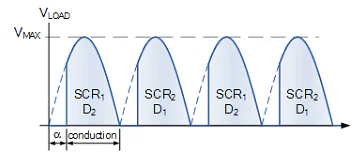
- During the positive half cycle of the input waveform, current flows along the path of: SCR1 and D2, and back to the supply. During the negative half cycle of VIN, conduction is through SCR2 and D1 and back to the supply.
- It is clear then that one thyristor from the top group (SCR1 or SCR2) and its corresponding diode from the bottom group (D2 or D1) must conduct together for for any load current to flow.
- Thus the average output voltage, VAVE is dependant on the firing angle α for the two thyristors included in the half-controlled rectifier as the two diodes are uncontrolled and pass current whenever forward biased. So for any gate firing angle, α, the average output voltage is given by:
Half-controlled Rectifier Average Output Voltage
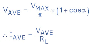
- Note that the maximum average output voltage occurs when α = 1 but is still only 0.637*VMAX the same as for the single phase uncontrolled bridge rectifier. We can take this idea of controlling the average output voltage of the bridge one step further by replacing all four diodes with thyristors giving us a Fully-controlled Bridge Rectifier circuit.
Fully-controlled Bridge Rectifier
- Single phase fully-controlled bridge rectifiers are known more commonly as AC-to-DC converters. Fully-controlled bridge converters are widely used in the speed control of DC machines and is easily obtained by replacing all four diodes of a bridge rectifier with thyristors as shown.
Fully-controlled Bridge Rectifier
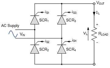
- In the fully-controlled rectifier configuration, the average DC load voltage is controlled using two thyristors per half-cycle. Thyristors SCR1 and SCR4 are fired together as a pair during the positive half-cycle, while thyristors SCR3 and SCR4 are also fired together as a pair during the negative half-cycle. That is 180o after SCR1 and SCR4.
- Then during continuous conduction mode of operation the four thyristors are constantly being switched as alternate pairs to maintain the average or equivalent DC output voltage. As with the half-controlled rectifier, the output voltage can be fully controlled by varying the thyristors firing delay angle (α).
- Thus the expression for the average DC voltage from a single phase fully-controlled rectifier in its continuous conduction mode is given as:
Fully-controlled Rectifier Average Output Voltage
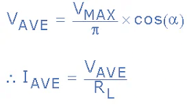
- with the average output voltage varying from VMAX/π to -VMAX/π by varying the firing angle, α from π to 0 respectively. So when α < 90o the average DC voltage is positive and when α > 90o the average DC voltage is negative. That is power flows from the DC load to the AC supply.
- Then we have seen here in this tutorial about single phase rectification that single phase rectifiers can take on many forms to convert AC voltage to DC voltage from uncontrolled single diode half-wave rectifiers to fully-controlled full-wave bridge rectifiers using four thyristors.
- The advantages of the half-wave rectifier are its simplicity and low cost as it requires only one diode. However, it is not very efficient as only half of the input signal is used producing a low average output voltage.
- The full-wave rectifier is more efficient than the half-wave rectifier as it uses both half-cycles of the input sine wave producing a higher average or equivalent DC output voltage. A disadvantage of the full-wave bridge circuit is that is that it requires four diodes.
- Phase controlled rectification uses combinations of diodes and thyristors (SCR’s) to convert the AC input voltage into a controlled DC output voltage. Fully-controlled rectifiers use four thyristors in their configuration, whereas half-controlled rectifiers use a combination of both thyristors and diodes.
|
5 videos|50 docs|46 tests
|

|
Explore Courses for Electrical Engineering (EE) exam
|

|


