Measurement of Self Inductance | GATE Notes & Videos for Electrical Engineering - Electrical Engineering (EE) PDF Download

Measurement of Self Inductance by Maxwell’s Inductance Bridge:
Maxwell’s inductance Bridge circuit measures an inductance by comparison with a variable standard self-inductance. The connections and the phasor diagrams for balance conditions are shown in the Maxwell’s Inductance Bridge figure.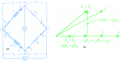
Let
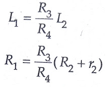
L1 = unknown inductance of resistance R1
L2 = variable inductance of fixed resistance r2
R2 = variable resistance connected in series with inductor L2
R3, R4 = known non-inductive resistances
The theory of Maxwell’s Inductance Bridge has been explained already in ac bridges post.
Resistors R3 and R4 are normally a selection of values from 10, 100, 1000 and 10,000 r2 is a decade resistance box. In some cases, an additional known resistance may have to be inserted in series with the unknown coil in order to obtain balance.
Measurement of Self Inductance by Maxwell’s Inductance Capacitance Bridge:
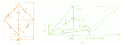
In Maxwell’s Inductance Capacitance Bridge, an inductance is measured by comparison. with a standard variable capacitance. The connections and the phasor diagram at the balance conditions are given in Maxwell’s Inductance Capacitance Bridge figure below:Let L1 = unknown inductance,
R1 = effective resistance of inductor L1,
R2, R3, R4 = known non-inductive resistances,
and C4 = variable standard capacitor.
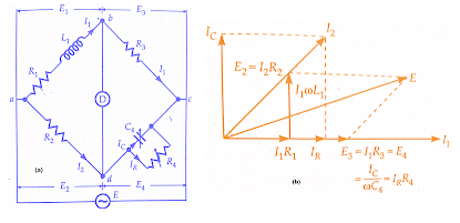
Writing the equation for balance
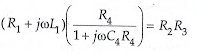
or 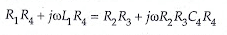
Separating the real and imaginary terms, we have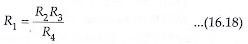
and 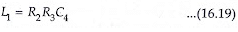
Thus we have two variables R4 and C4 which appear in one of the two balance equations and hence the two equations are independent.
The expression for Q factor,
Q = ωL₁/R₁ = ωC₄R₄
Advantages of Maxwell’s Inductance Capacitance Bridge
- The two balance equations are independent if we choose R4 and C 4 as variable elements.
- The frequency does not appear in any of the two equations.
- Maxwell’s Inductance Capacitance Bridge yields a simple expression for unknowns L1 and R1 in terms of known bridge elements.
Physically R2 and R3 are each, say, 10, 100,1000 or 10,000 Q and their value is selected to give suitable value of product R2R3 which appears in both the balance equations; C4 is decade capacitor and R4 a decade resistor.
The simplicity of the bridge can be appreciated by the following example. Suppose the product R2R3 is 10⁶.Therefore, inductance is L1= C4 x 10⁶. Thus when the balance is achieved the value of C4 in μF directly gives the value of inductance in H. - The Maxwell’s inductance capacitance bridge is very useful for measurement of a wide range of inductance at the power and audio frequencies.
Disadvantages of Maxwell’s Inductance Capacitance Bridge
- Maxwell’s Inductance Capacitance Bridge requires a variable standard capacitor which may be very expensive if calibrated to a high degree of accuracy.Therefore sometimes a fixed standard capacitor is used, either because a variable capacitor is not available or because fixed capacitors have a higher degree of accuracy and are less expensive than the variable ones. The balance adjustments are then done by
(a) either varying R2 and R4 and since R2 appears in both the balance equations, the balance adjustments become difficult
(b) putting an additional resistance in series with the inductance under measurement and then varying this resistance and R4. - The bridge is limited to measurement of low Q coils, (1 < Q < 10). It is clear that the measurement of high Q coils demands a large value for resistance R4, perhaps 10⁵ or 10⁶. The resistance boxes of such high values are very expensive. Thus for values of Q > 10, Maxwell’s bridge is unsuitable.
- The Maxwell’s bridge is also unsuited for coils with a very low value of Q (i.e., Q < 1). Q values of this magnitude occur in inductive resistors, or in an R.F. coil if measured at low frequencies. The difficulty in measurement occurs on account of labour involved in obtaining balance since nominally a fixed capacitor is used and balance is obtained by manipulating resistances R2 and R4 alternately. This difficulty is explained as below:
- A preliminary inductive balance is made with R2 and then R4 is varied to give a resistive balance which is dependent on the R2 setting. Accordingly, when R2 is changed for a second inductive balance, the resistive balance is disturbed and moves to a new value giving slow “convergence” to balance. This is particularly true of a low Q coil, for which resistance is prominent (as = wL/ R).
- Thus a sliding balance condition prevails and it takes many manipulations to achieve balance for low Q coils with Maxwell’s bridge. From the above discussions, we conclude that Maxwell’s bridge is suited for measurements of only medium Q coils.
Measurement of Self Inductance By Anderson’s Bridge
Anderson’s Bridge, in fact, is a modification of Maxwell’s inductance capacitance bridge.In Anderson’s Bridge, the self inductance is measured in terms of a standard capacitor.
Anderson’s Bridge is usefully applicable for precise measurement of self inductance over a very wide range of values. The below figure shows the connections and the phasor diagram of the bridge for balanced conditions.
Let L1 = self-inductance to be measured,
R1 = resistance of self-inductor,
r = resistance connected in series with self-inductor,
r, R2, R3, R4 = known non-inductive resistances, and
C = fixed standard capacitor
At balance,
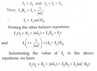
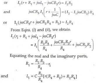
An examination of balance equations reveals that to obtain easy convergence of balance, alternate adjustments of r1 and r should be done as they appear in only one of the two balance equations.
Advantages of Anderson’s Bridge
- In case adjustments are carried out by manipulating control over r1 and r, they become independent of each other.This is a marked superiority over sliding balance conditions met with low Q coils when measuring with Maxwell’s bridge. A study of convergence conditions would reveal that it is much easier to obtain balance in the case of Anderson’s bridge than in Maxwell’s bridge for low Q-coils.
- A fixed capacitor can be used instead of a variable capacitor as in the case of Maxwell’s bridge.
- Anderson’s Bridge may be used for accurate determination of capacitance in terms of inductance.
Disadvantages of Anderson’s Bridge
- The Anderson’s bridge is more complex than its prototype Maxwell’s bridge. The Anderson’s bridge has more parts and is more complicated to set up and manipulate. The balance equations are not simple and in fact are much more tedious.
- An additional junction point increases the difficulty of shielding the bridge.
Measurement of Self Inductance by Owen’s Bridge
Owen’s bridge may be used for the measurement of inductance in terms of capacitance. The below figure shows the connections and phasor diagrams, for Owen’s bridge, under balance conditions.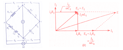
Let
L1 = unknown self-inductance of resistance
R2 = variable non-inductive resistance,
R3 = fixed non-inductive resistance,
C2 = variable standard capacitor,
C4 = fixed standard capacitor
At balance,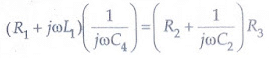 Separating the real and imaginary terms, we have
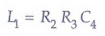
and
Advantages of Owen’s Bridge
- Examining the equations for balance, We find that we obtain two independent equations in case C2 and R2 are made variable. Since R2 and C2, the variable elements, are in the same arm, convergence to balance conditions is much easier.
- The balance equations are quite simple and do not contain any frequency component.
- Owen’s Bridge can be used over a wide range of measurement of inductances.
Disadvantages of Owen’s Bridge
- Owen’s bridge requires a variable capacitor which is an expensive item and also its accuracy is about 1 per cent.
- The value of capacitance C2 tends to become rather large when measuring high Q coils.
Heaviside Mutual Inductance Bridge
Heaviside Bridge measures mutual inductance in terms of a known self-inductance. The same bridge, slightly modified, was used by Campbell to measure a self-inductance in terms of a known mutual inductance.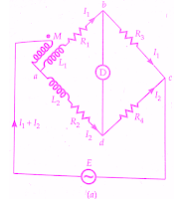
Measurement of Mutual Inductance By Heaviside Bridge
Let M = unknown mutual inductance,
L1 = self-inductance of secondary of mutual inductance,
L2 =known self-inductance, and
R1, R2, R3, R4 = non-inductive resistors.
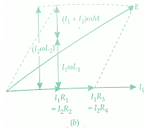
At balance voltage drop between b and c must equal the voltage drop between d and c. Also, the voltage drop across a-b-c must equal the voltage drop across a-d-c. Thus we have the following equations at balance.
It is clear from the above equation, that L1, the self inductance of the secondary of the mutual inductor must be known in order that M be measured by this Heaviside Bridge method.
In case R3 = R4
we get M = (L2 - L1)/2 and R1= R2
Heaviside Bridge method can be used for measurement of self-inductance. Supposing L2 is the self-inductance to be determined. From above equations, we get
Campbell’s Modification of Heaviside Bridge
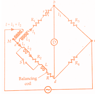
- The below figure shows a modified Heaviside bridge. This modification is due to Campbell. This is used to measure a self-inductance in terms of a mutual inductance. In this case, an additional balancing coil R is included in arm a-d in series with inductor under test. An additional resistance r is put in arm a-b. Balance is obtained by varying M and r.
- A short circuiting switch is placed across the coil R2, L2 under measurement. Two sets of readings are taken one with switch being open and the other with switch being closed. Let values of M and r, be M1 and r1 with switch open, and M2 and r2 with switch closed.
With switch open from above equation we have,
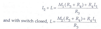
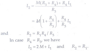
Hence L2 = (M1 M2)(1 + R4/R3)
With switch open, we have, R2+ R = (R1 + r1)R4/R3
and with the switch closed
R = (R1 + r2)R4/R3
R2 = (r1 - r2) R4/R3
This method is a good example of the methods adopted to eliminate the effects of leads etc.
When we have equal ratio arms R3 = R4
and therefore from above equations we get,
L2 = (M1 - M2) and R2 = (r1 - r2)
Heaviside Campbell Equal Ratio Bridge
The use of balancing coil in the above method reduces the sensitivity of the bridge.The below figure shows Heaviside Campbell equal ratio bridge. This is a better arrangement which improves sensitivity and also dispenses with the use of a balancing coil.In this method, the secondary of the mutual inductor is made up of two equal coils each having a self-inductance.
- One of the coils is connected in arm ab and the other in arm a-d.The primary of mutual inductance reacts with both of them.L2, R2 is the coil whose self-inductance and resistance is to be determined.The resistances R3 and R4 are made equal.Balance is obtained by varying the mutual inductance and resistance r.
At balance I1R3 = I2R4 but R3 = R4
and therefore I1 = I2 = I/2 as I = I1 + I2
Writing the other equation for balance
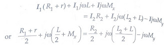
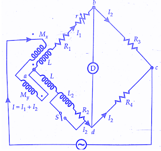 Equating the real and imaginary terms
R2 = R1 + r and L2 =2(Mx + My)=2M
Thus the magnitude of inductance measured with this method is twice the range of the mutual inductor. The values calculated above include the effects of leads etc. In order to eliminate these effects, we take two readings with the switch open circuited and another with the switch closed. Let M1, r1 be the readings of M, r with open circuit and M2, r2 with the short circuit.
R1 = (r1-r2) and L1 = 2(M1-M2)
|
28 videos|333 docs
|


mock tests for examination
,Measurement of Self Inductance | GATE Notes & Videos for Electrical Engineering - Electrical Engineering (EE)
,Measurement of Self Inductance | GATE Notes & Videos for Electrical Engineering - Electrical Engineering (EE)
,Summary
,Extra Questions
,Important questions
,video lectures
,Viva Questions
,Previous Year Questions with Solutions
,Objective type Questions
,past year papers
,Semester Notes
,Exam
,Sample Paper
,Measurement of Self Inductance | GATE Notes & Videos for Electrical Engineering - Electrical Engineering (EE)
,MCQs
,shortcuts and tricks
,practice quizzes
,ppt
,Free
,study material
;


Measurement of Self Inductance Free PDF Download
Importance of Measurement of Self Inductance
Measurement of Self Inductance Notes
Measurement of Self Inductance Electrical Engineering (EE) Questions
Study Measurement of Self Inductance on the App
|
© EduRev
|
Education Revolution
|


|


