Master Slave J-K & D Flip Flop | Digital Circuits - Electronics and Communication Engineering (ECE) PDF Download
The JK Type Master-Slave Flip-Flop
In "JK Flip Flop", when both the inputs and CLK set to 1 for a long time, then Q output toggle until the CLK is 1. Thus, the uncertain or unreliable output produces. This problem is referred to as a race-round condition in JK flip-flop and avoided by ensuring that the CLK set to 1 only for a very short time.

Explanation
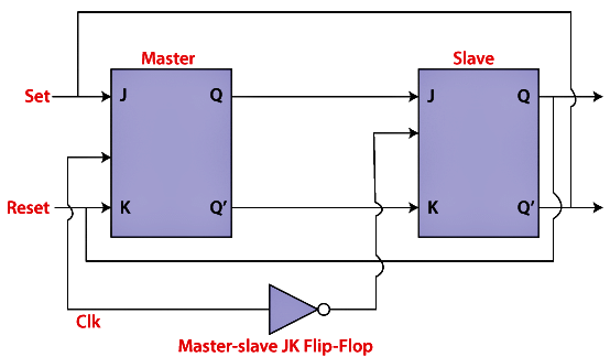
- The master-slave flip flop is constructed by combining two JK flip flops. These flip flops are connected in a series configuration. In these two flip flops, the 1st flip flop work as "master", called the master flip flop, and the 2nd work as a "slave", called slave flip flop. The master-slave flip flop is designed in such a way that the output of the "master" flip flop is passed to both the inputs of the "slave" flip flop. The output of the "slave" flip flop is passed to inputs of the master flip flop.
- In "master-slave flip flop", apart from these two flip flops, an inverter or NOT gate is also used. For passing the inverted clock pulse to the "slave" flip flop, the inverter is connected to the clock's pulse. In simple words, when CP set to false for "master", then CP is set to true for "slave", and when CP set to true for "master", then CP is set to false for "slave".
 |
Test: Master Slave Flip Flop
|
Start Test |
Working:
- When the clock pulse is true, the slave flip flop will be in the isolated state, and the system's state may be affected by the J and K inputs. The "slave" remains isolated until the CP is 1. When the CP set to 0, the master flip-flop passes the information to the slave flip flop to obtain the output.
- The master flip flop responds first from the slave because the master flip flop is the positive level trigger, and the slave flip flop is the negative level trigger.
- The output Q'=1 of the master flip flop is passed to the slave flip flop as an input K when the input J set to 0 and K set to 1. The clock forces the slave flip flop to work as reset, and then the slave copies the master flip flop.
- When J=1, and K=0, the output Q=1 is passed to the J input of the slave. The clock's negative transition sets the slave and copies the master.
- The master flip flop toggles on the clock's positive transition when the inputs J and K set to 1. At that time, the slave flip flop toggles on the clock's negative transition.
- The flip flop will be disabled, and Q remains unchanged when both the inputs of the JK flip flop set to 0.
Timing Diagram of a Master Flip Flop:
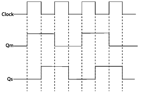
- When the clock pulse set to 1, the output of the master flip flop will be one until the clock input remains 0.
- When the clock pulse becomes high again, then the master's output is 0, which will be set to 1 when the clock becomes one again.
- The master flip flop is operational when the clock pulse is 1. The slave's output remains 0 until the clock is not set to 0 because the slave flip flop is not operational.
- The slave flip flop is operational when the clock pulse is 0. The output of the master remains one until the clock is not set to 0 again.
- Toggling occurs during the entire process because the output changes once in the cycle.
The D Type Master Slave Flip-Flop
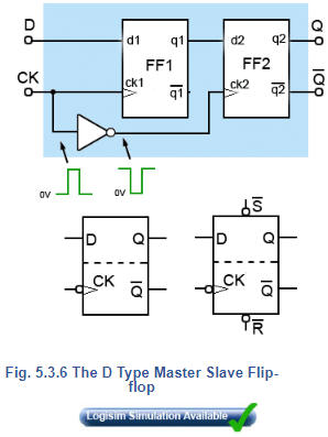
Yet a further version of the D Type flip-flop is shown in Fig. 5.3.6 where two D type flip-flops are incorporated in a single device, this is the D type master-slave flip-flop. Circuit symbols for the master-slave device are very similar to those for edgetriggered flip-flops, but are now divided into two sections by a dotted line, as also illustrated in Fig 5.3.6.
FF1 (the master flip-flop) is a positive edge triggered device, and an inverted version of the CK pulse is fed from the main CK input to FF2 (the slave), also positive edge triggered. Notice that although the clock inputs on the circuit symbols suggest that this is a negative edge triggered device, data is actually taken into FF1 on the POSITIVE going edge of the CK pulse. The data also of course appears at q1 at this time, but as the CK pulse is inverted at ck2, FF2 is seeing a falling edge at the same time, so ignores the data on d2.
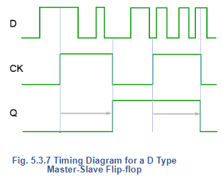
After the positive going edge of the external CK pulse, FF1 ignores any further data at D, and at the negative going edge of the external CK pulse, the data being held at q1 is taken into the d2 input of FF2 which now sees a positive going edge of the inverted CK pulse. Therefore data is taken into D at the positive going (rising) edge of the CK pulse, and then appears at Q at the negative going (falling) edge of the CK pulse.
Considering the master slave flip-flop as a single device, the relationship between the clock (CK) input and the Q output does look rather like a negative edge triggered device, as any change in the output occurs at the falling edge of the clock pulse. However, as illustrated in Fig. 5.3.7 this is not really negative edge triggering, because the data appearing at Q as the clock pulse returns to logic 0, is actually the data that was present at input D at the RISING edge of the CK pulse. Any further changes that may occur in data at the D input during the clock pulse are ignored. D type master-slave flip-flops are also available with asynchronous  inputs making it a very versatile device indeed.
|
8 videos|79 docs|52 tests
|
FAQs on Master Slave J-K & D Flip Flop - Digital Circuits - Electronics and Communication Engineering (ECE)
| 1. What is a Master-Slave JK Flip-Flop and how does it work? |  |
| 2. How does the D Type Master-Slave Flip-Flop differ from the JK Flip-Flop? | |
| 3. What are the primary applications of Master-Slave JK and D Flip-Flops? | |
| 4. What are the advantages of using Master-Slave Flip-Flops in digital circuits? | |
| 5. Can Master-Slave JK and D Flip-Flops be used interchangeably in circuits? | |


video lectures
,practice quizzes
,MCQs
,Previous Year Questions with Solutions
,mock tests for examination
,Viva Questions
,Master Slave J-K & D Flip Flop | Digital Circuits - Electronics and Communication Engineering (ECE)
,Master Slave J-K & D Flip Flop | Digital Circuits - Electronics and Communication Engineering (ECE)
,study material
,Semester Notes
,Sample Paper
,Master Slave J-K & D Flip Flop | Digital Circuits - Electronics and Communication Engineering (ECE)
,Important questions
,Extra Questions
,ppt
,shortcuts and tricks
,past year papers
,Summary
,Exam
,Free
,Objective type Questions
;


Master Slave J-K & D Flip Flop Free PDF Download
Importance of Master Slave J-K & D Flip Flop
Master Slave J-K & D Flip Flop Notes
Master Slave J-K & D Flip Flop Electronics and Communication Engineering (ECE) Questions
Study Master Slave J-K & D Flip Flop on the App
|
© EduRev
|
Education Revolution
|


|


