Ring Counter & Johnson Counter | Digital Circuits - Electronics and Communication Engineering (ECE) PDF Download

Introduction
Counters are fundamental components in digital electronics, widely utilized for sequencing, timing, and state management in various applications. Among the diverse array of counter designs, the Ring counter and the Johnson counter emerge as notable variants, both derived from the principles of shift registers. The Ring counter is distinguished by its elegant simplicity, employing a circular feedback mechanism to propagate a single active bit across a series of flip-flops, thereby generating a predictable sequence of states. In contrast, the Johnson counter introduces a sophisticated twist by feeding the inverted output of the last flip-flop back to the first, doubling the number of usable states while retaining the same number of flip-flops. This paper explores the operational principles, structural differences, and practical implications of these two counters, offering a comprehensive understanding of their design and functionality in modern digital systems.
Ring Counter
A ring counter is a special type of application of the Serial IN Serial OUT Shift register. The only difference between the shift register and the ring counter is that the last flip flop outcome is taken as the output in the shift register. But in the ring counter, this outcome is passed to the first flip flop as an input. All of the remaining things in the ring counter are the same as the shift register.
In the Ring counter
No. of states in Ring counter = No. of flip-flop used
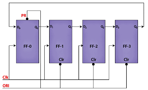
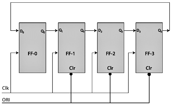
Below is the block diagram of the 4-bit ring counter. Here, we use 4 D flip flops. The same clock pulse is passed to the clock input of all the flip flops as a synchronous counter. The Overriding input(ORI) is used to design this circuit.
The Overriding input is used as clear and pre-set.
The output is 1 when the pre-set set to 0. The output is 0 when the clear set to 0. Both PR and CLR always work in value 0 because they are active low signals.
PR = 0, Q = 1
CLR = 0, Q = 0
These two values(always fixed) are independent with the input D and the Clock pulse (CLK).
Working
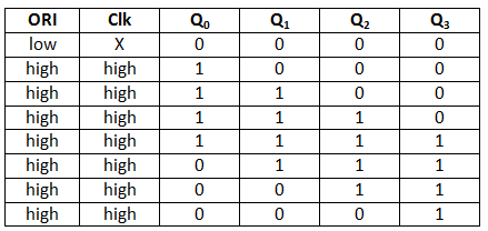
The ORI input is passed to the PR input of the first flip flop, i.e., FF-0, and it is also passed to the clear input of the remaining three flip flops, i.e., FF-1, FF-2, and FF-3. The pre-set input set to 0 for the first flip flop. So, the output of the first flip flop is one, and the outputs of the remaining flip flops are 0. The output of the first flip flop is used to form the ring in the ring counter and referred to as Pre-set 1.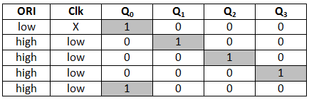
In the above table, the highlighted 1's are pre-set 1.
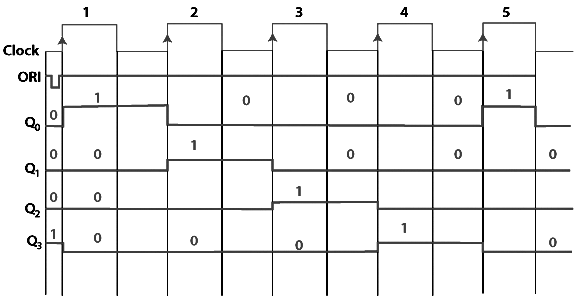
The Pre-set 1 is generated when
- ORI input set to low, and that time the Clk doesn't care.
- When the ORI input set to high, and the low clock pulse signal is passed as the negative clock edge triggered.
- A ring forms when the pre-set 1 is shifted to the next flip-flop at each clock pulse.
So, 4-bit counter, 4 states are possible which are as follows:
1 0 0 0
0 1 0 0
0 0 1 0
0 0 0 1
Types of Ring Counter
The ring counter is classified into two parts which are as follows:
Straight Ring Counter
The Straight Ring Counter refers to as One hot Counter. The outcome of the last flip-flop is passed to the first flip-flop as an input. In the ring counter, the ORI input is passed to the PR input for the first flip flop and to the clear input of the remaining flip flops.
Note: The straight ring counter circulates the single 1 (or 0) bit around the ring.
Logic Diagram
Truth Table
Signal Diagram
Twisted Ring Counter
The Twisted Ring Counter refers to as a switch-tail ring Counter. Like the straight ring counter, the outcome of the last flip-flop is passed to the first flip-flop as an input. In the twisted ring counter, the ORI input is passed to all the flip flops as clear input.
Note: The twisted ring counter circulates a stream of 1's followed by 0 around the ring.
Logic Diagram
Truth Table
Signal Diagram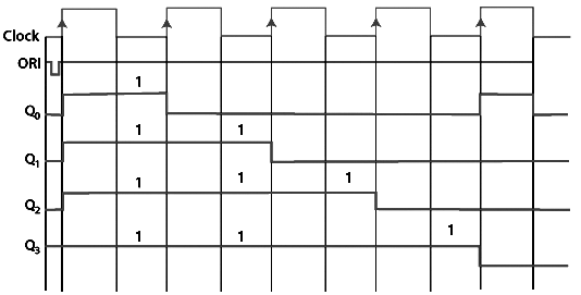
Jhonson Counter
The Johnson counter is similar to the Ring counter. The only difference between the Johnson counter and the ring counter is that the outcome of the last flip flop is passed to the first flip flop as an input. But in Johnson counter, the inverted outcome Q' of the last flip flop is passed as an input. The remaining work of the Johnson counter is the same as a ring counter. The Johnson counter is also referred to as the Creeping counter.
In Johnson counter
No. of states in Johnson counter = No. of flip-flop used
Number of used states=2n
Number of unused states=2n - 2*n
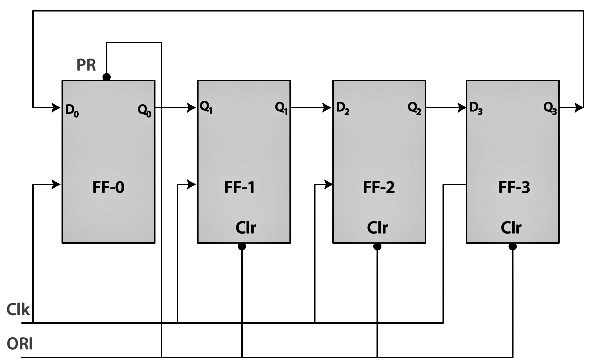
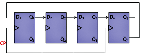
Below is the diagram of the 4-bit Johnson counter. Like Ring counter, four D flip flops are used in the 4-bit Johnson counter, and the same clock pulse is passed to all the input of the flip flops.
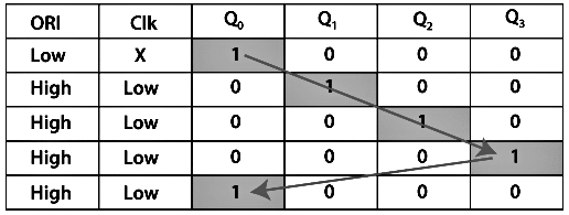
Truth Table
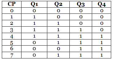
The above table state that
- The counter produces the output 0000 when there is no clock input passed(0).
- The counter produces the output 1000 when the 1st clock pulse is passed to the flip flops.
- The counter produces the output 1100 when the 2nd clock pulse is passed to the flip flops.
- The counter produces the output 1110 when the 3rd clock pulse is passed to the flip flops.
- The counter produces the output 1111 when the 4th clock pulse is passed to the flip flops.
- The counter produces the output 0111 when the 5th clock pulse is passed to the flip flops.
- The counter produces the output 0011 when the 6th clock pulse is passed to the flip flops.
- The counter produces the output 0001 when the 7th clock pulse is passed to the flip flops.
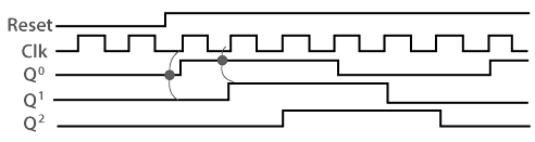
Timing diagram
Advantage
- The number of flip flops in the Johnson counter is equal to the number of flip flops in the ring counter, and the Johnson counter counts twice the number of states the ring counter can count.
- The Johnson counter can also be designed by using D or JK flip flop.
- The data is count in a continuous loop in the Johnson ring counter.
- The circuit of the Johnson counter is self-decoding.
Disadvantages
- The Johnson counter is not able to count the states in a binary sequence.
- In the Johnson counter, the unutilized states are greater than the states being utilized.
- The number of flip flops is equal to one half of the number of timing signals.
- It is possible to design the Johnson counter for any number of timing sequences.
Conclusion
In summary, the Ring counter and Johnson counter represent two distinct yet complementary approaches to state generation within digital circuits. The Ring counter, with its straightforward architecture, provides an efficient solution for applications requiring a limited, cyclic sequence of states, leveraging a minimalistic design to achieve reliable performance. Conversely, the Johnson counter enhances versatility by maximizing the number of states through its innovative use of inverted feedback, making it a preferred choice for scenarios demanding extended sequences without additional hardware. While the Ring counter excels in simplicity and directness, the Johnson counter offers a trade-off between increased state capacity and the presence of unused states, highlighting their respective strengths and limitations. Together, these counters exemplify the adaptability of shift register-based designs, providing engineers and designers with valuable tools to address diverse timing and sequencing challenges in digital electronics.
|
76 videos|175 docs|70 tests
|
FAQs on Ring Counter & Johnson Counter - Digital Circuits - Electronics and Communication Engineering (ECE)
| 1. What is a ring counter and how does it operate? |  |
| 2. What are the differences between a ring counter and a Johnson counter? | |
| 3. What are the applications of ring counters in digital circuits? | |
| 4. How many states does a ring counter with N flip-flops have? | |
| 5. Can a ring counter be reset, and if so, how? | |


Ring Counter & Johnson Counter | Digital Circuits - Electronics and Communication Engineering (ECE)
,ppt
,Objective type Questions
,study material
,mock tests for examination
,Sample Paper
,practice quizzes
,past year papers
,video lectures
,Extra Questions
,Previous Year Questions with Solutions
,Important questions
,shortcuts and tricks
,MCQs
,Exam
,Viva Questions
,Summary
,Ring Counter & Johnson Counter | Digital Circuits - Electronics and Communication Engineering (ECE)
,Ring Counter & Johnson Counter | Digital Circuits - Electronics and Communication Engineering (ECE)
,Semester Notes
,Free
;


Ring Counter & Johnson Counter Free PDF Download
Importance of Ring Counter & Johnson Counter
Ring Counter & Johnson Counter Notes
Ring Counter & Johnson Counter Electronics and Communication Engineering (ECE) Questions
Study Ring Counter & Johnson Counter on the App
|
© EduRev
|
Education Revolution
|


|


