Decoder

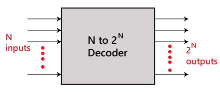
The combinational circuit that change the binary information into 2N output lines is known as Decoders. The binary information is passed in the form of N input lines. The output lines define the 2N-bit code for the binary information. In simple words, the Decoder performs the reverse operation of the Encoder. At a time, only one input line is activated for simplicity. The produced 2N-bit output code is equivalent to the binary information.
 There are various types of decoders which are as follows:
2 to 4 line decoder
In the 2 to 4 line decoder, there is a total of three inputs, i.e., A0, and A1 and E and four outputs, i.e., Y0, Y1, Y2, and Y3. For each combination of inputs, when the enable 'E' is set to 1, one of these four outputs will be 1. The block diagram and the truth table of the 2 to 4 line decoder are given below.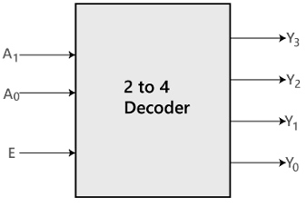 Block Diagram
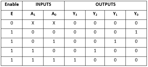 Truth Table
The logical expression of the term Y0, Y0, Y2, and Y3 is as follows:
Y3 = E.A1.A0
Y2 = E.A1.A0'
Y1 = E.A1'.A0
Y0 = E.A1'.A0'
Logical circuit of the above expressions is given below: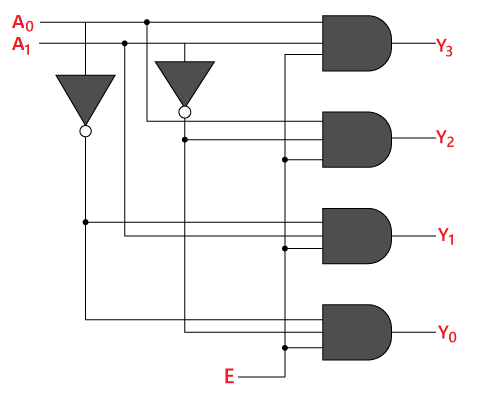
3 to 8 line decoder
The 3 to 8 line decoder is also known as Binary to Octal Decoder. In a 3 to 8 line decoder, there is a total of eight outputs, i.e., Y0, Y1, Y2, Y3, Y4, Y5, Y6, and Y7 and three outputs, i.e., A0, A1, and A2. This circuit has an enable input 'E'. Just like 2 to 4 line decoder, when enable 'E' is set to 1, one of these four outputs will be 1. The block diagram and the truth table of the 3 to 8 line encoder are given below.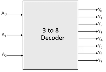 Block Diagram
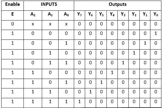 Truth Table
The logical expression of the term Y0, Y1, Y2, Y3, Y4, Y5, Y6, and Y7 is as follows:
Y0 = A0'.A1'.A2'
Y1= A0.A1'.A2'
Y2 = A0'.A1.A2'
Y3 = A0.A1.A2'
Y4 = A0'.A1'.A2
Y5 = A0.A1'.A2
Y6 = A0'.A1.A2
Y7 = A0.A1.A2
Logical circuit of the above expressions is given below: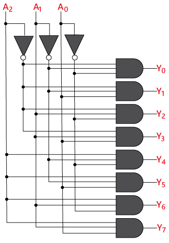
4 to 16 line Decoder
In the 4 to 16 line decoder, there is a total of 16 outputs, i.e., Y0, Y1, Y2,......, Y16 and four inputs, i.e., A0, A1, A2, and A3. The 3 to 16 line decoder can be constructed using either 2 to 4 decoder or 3 to 8 decoder. There is the following formula used to find the required number of lower-order decoders.Required number of lower order decoders = m2/m1
m1 = 8
m2 = 16
Required number of 3 to 8 decoders=Decoder=2
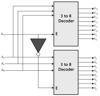 Block Diagram
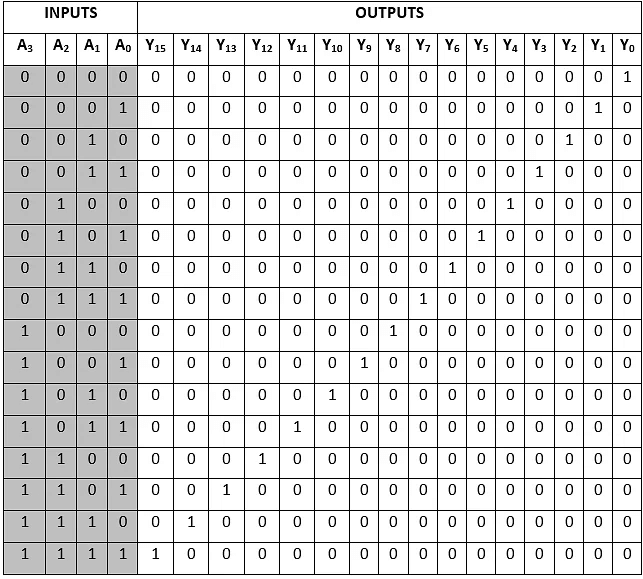 Truth Table
The logical expression of the term A0, A1, A2,..., A15 are as follows:
Y0 = A0'.A1'.A2'.A3'
Y1 = A0'.A1'.A2'.A3
Y2 = A0'.A1'.A2.A3'
Y3 = A0'.A1'.A2.A3
Y4 = A0'.A1.A2'.A3'
Y5 = A0'.A1.A2'.A3
Y6 = A0'.A1.A2.A3'
Y7 = A0'.A1.A2.A3
Y8 = A0.A1'.A2'.A3'
Y9 = A0.A1'.A2'.A3
Y10 = A0.A1'.A2.A3'
Y11 = A0.A1'.A2.A3
Y12 = A0.A1.A2'.A3'
Y13 = A0.A1.A2'.A3
Y14 = A0.A1.A2.A3'
Y15 = A0.A1.A2'.A3
Logical circuit of the above expressions is given below: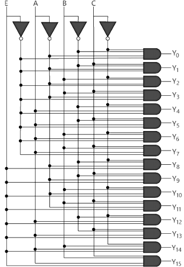
FAQs on Decoder
| 1. What is a Decoder GATE and how does it function in digital circuits? |  |
| 2. What are the main applications of Decoder GATES in electronics? | |
| 3. How is a Decoder GATE different from an Encoder? | |
| 4. Can you explain the truth table of a basic 2-to-4 Decoder? | |
| 5. What are the advantages of using Decoder GATES in circuit design? | |


 | Explore Courses for Electronics and Communication Engineering (ECE) exam |
 | Get EduRev Notes directly in your Google search |