Demultiplexer | Digital Circuits - Electronics and Communication Engineering (ECE) PDF Download

About De-multiplexer
- A De-multiplexer is a combinational circuit that has only 1 input line and 2N output lines. Simply, the multiplexer is a single-input and multi-output combinational circuit. The information is received from the single input lines and directed to the output line. On the basis of the values of the selection lines, the input will be connected to one of these outputs. De-multiplexer is opposite to the multiplexer.
- Unlike encoder and decoder, there are n selection lines and 2n outputs. So, there is a total of 2n possible combinations of inputs. De-multiplexer is also treated as De-mux.
There are various types of De-multiplexer which are as follows:
1×2 De-multiplexer
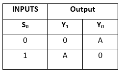
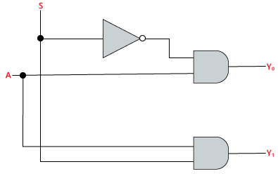
In the 1 to 2 De-multiplexer, there are only two outputs, i.e., Y0, and Y1, 1 selection lines, i.e., S0, and single input, i.e., A. On the basis of the selection value, the input will be connected to one of the outputs. The block diagram and the truth table of the 1×2 multiplexer are given below.Block Diagram

Truth Table:
 The logical expression of the term Y is as follows:
Y0 = S0'.A
Y1 = S0 A
Logical circuit of the above expressions is given below:
 1×4 De-multiplexer
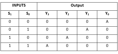
In 1 to 4 De-multiplexer, there are total of four outputs, i.e., Y0, Y1, Y2, and Y3, 2 selection lines, i.e., S0 and S1 and single input, i.e., A. On the basis of the combination of inputs which are present at the selection lines S0 and S1, the input be connected to one of the outputs. The block diagram and the truth table of the 1×4 multiplexer are given below.Block Diagram

Truth Table
 The logical expression of the term Y is as follows:
Y0 = S1' S0' A
y1 = S1' S0 A
y2 = S1 S0' A
y3 = S1 S0 A
Logical circuit of the above expressions is given below:
1×8 De-multiplexer
In 1 to 8 De-multiplexer, there are total of eight outputs, i.e., Y0, Y1, Y2, Y3, Y4, Y5, Y6, and Y7, 3 selection lines, i.e., S0, S1and S2 and single input, i.e., A. On the basis of the combination of inputs which are present at the selection lines S0, S1 and S2, the input will be connected to one of these outputs. The block diagram and the truth table of the 1×8 de-multiplexer are given below.Block Diagram
Truth Table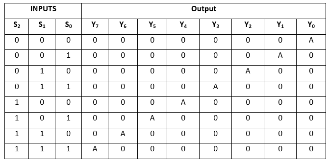 The logical expression of the term Y is as follows:
Y0 = S0'.S1'.S2'.A
Y1 = S0.S1'.S2'.A
Y2 = S0'.S1.S2'.A
Y3 = S0.S1.S2'.A
Y4 = S0'.S1'.S2 A
Y5 = S0.S1'.S2 A
Y6 = S0'.S1.S2 A
Y7 = S0.S1.S3.A
Logical circuit of the above expressions is given below:
1×8 De-multiplexer using 1×4 and 1×2 de-multiplexer
- We can implement the 1×8 de-multiplexer using a lower order de-multiplexer. To implement the 1×8 de-multiplexer, we need two 1×4 de-multiplexer and one 1×2 de-multiplexer. The 1×4 multiplexer has 2 selection lines, 4 outputs, and 1 input. The 1×2 de-multiplexer has only 1 selection line.
- For getting 8 data outputs, we need two 1×4 de-multiplexer. The 1×2 de-multiplexer produces two outputs. So, in order to get the final output, we have to pass the outputs of 1×2 de-multiplexer as an input of both the 1×4 de-multiplexer. The block diagram of 1×8 de-multiplexer using 1×4 and 1×2 de-multiplexer is given below.

1 x 16 De-multiplexer
In 1×16 de-multiplexer, there are total of 16 outputs, i.e., Y0, Y1, …, Y16, 4 selection lines, i.e., S0, S1, S2, and S3 and single input, i.e., A. On the basis of the combination of inputs which are present at the selection lines S0, S1, and S2, the input will be connected to one of these outputs. The block diagram and the truth table of the 1×16 de-multiplexer are given below.
Block Diagram

Truth Table The logical expression of the term Y is as follows:
Y0 = A.S0'.S1'.S2'.S3'
Y1 = A.S0'.S1'.S2'.S3
Y2 = A.S0'.S1'.S2.S3'
Y3 = A.S0'.S1'.S2.S3
Y4 = A.S0'.S1.S2'.S3'
Y5 = A.S0'.S1.S2'.S3
Y6 = A.S0'.S1.S2.S3'
Y7 = A.S0'.S1.S2.S3
Y8 = A.S0.S1'.S2'.S3'
Y9 = A.S0.S1'.S2'.S3
Y10 = A.S0.S1'.S2.S3'
Y11 = A.S0.S1'.S2.S3
Y12 = A.S0.S1.S2'.S3'
Y13 = A.S0.S1.S2'.S3
Y14 = A.S0.S1.S2.S3'
Y15 = A.S0.S1.S2'.S3
Logical circuit of the above expressions is given below:
1×16 de-multiplexer using 1×8 and 1×2 de-multiplexer
We can implement the 1×16 de-multiplexer using a lower order de-multiplexer. To implement the 1×16 de-multiplexer, we need two 1×8 de-multiplexer and one 1×2 de-multiplexer. The 1×8 multiplexer has 3 selection lines, 1 input, and 8 outputs. The 1×2 de-multiplexer has only 1 selection line.For getting 16 data outputs, we need two 1×8 de-multiplexer. The 1×8 de-multiplexer produces eight outputs. So, in order to get the final output, we need a 1×2 de-multiplexer to produce two outputs from a single input. Then we pass these outputs into both the de-multiplexer as an input. The block diagram of 1×16 de-multiplexer using 1×8 and 1×2 de-multiplexer is given below.
|
75 videos|188 docs|70 tests
|


Demultiplexer | Digital Circuits - Electronics and Communication Engineering (ECE)
,Sample Paper
,Semester Notes
,Extra Questions
,ppt
,Demultiplexer | Digital Circuits - Electronics and Communication Engineering (ECE)
,Previous Year Questions with Solutions
,Objective type Questions
,past year papers
,Exam
,study material
,Viva Questions
,video lectures
,Summary
,shortcuts and tricks
,Demultiplexer | Digital Circuits - Electronics and Communication Engineering (ECE)
,practice quizzes
,Important questions
,MCQs
,mock tests for examination
,Free
;


Demultiplexer Free PDF Download
Importance of Demultiplexer
Demultiplexer Notes
Demultiplexer Electronics and Communication Engineering (ECE) Questions
Study Demultiplexer on the App
|
© EduRev
|
Education Revolution
|


|


