Series & Parallel Circuits | Physics for Grade 12 PDF Download
Power
Electrical Power
- In mechanics, power P is defined as the rate of doing work
- Potential difference is the work done per unit charge
- Current is the rate of flow of charge
- The electrical power dissipated (produced) by an electrical device is defined by the equation:
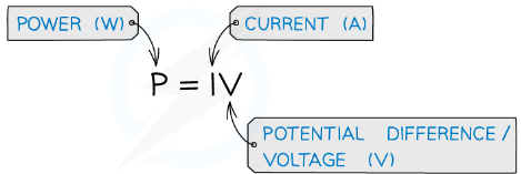
- The unit of power is Watt (W)
- Using Ohm's Law V = IR to rearrange for either V or I and substituting into the power equation, means power can be written in terms of resistance R

- This means for a given resistor if the current or voltage doubles the power will be four times as great
Example: Two lamps are connected in series to a 150 V power supply.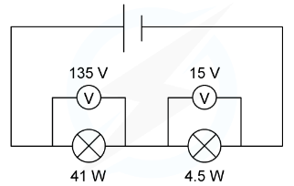 Which statement most accurately describes what happens?
(a) Both lamps light normally
(b) The 15 V lamp blows
(c) Only the 41 W lamp lights
(d) Both lamps light at less than their normal brightness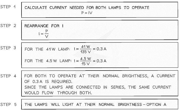
Electrical Energy Transfer
- The electrical power is also defined as the rate of change of work done:
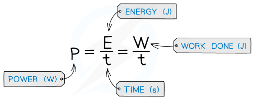
- The work done is the energy transferred
- The power is, therefore, the energy transferred per second in an electrical component
- Rearranging the energy and power equation, the energy can be written as:
W = Pt = IVt - Where:
- W = Work done / energy transferred (J)
- P = power (W)
- V = voltage (V)
- I = current (A)
- t = time (s)
Calculating the Cost of Energy & The Kilowatt-hour (kWh)
The power of an appliance is:
The amount of energy transferred (by electrical work) to the device every second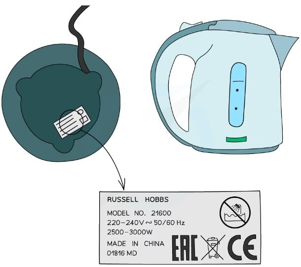 The power consumption of an electrical appliance can be found on a label that looks like this. This kettle uses between 2500 and 3000 W of electrical energy
- This energy is commonly measured in kilowatt-hour (kW h), which is then used to calculate the cost of energy
- This is used to calculate electricity bills
- A kilowatt-hour is defined as:
A unit of energy equal to 1 kW of power sustained for 1 hour - Or as an equation:
Energy (kW h) = Power (kW) × Time (h) - Since the usual unit of energy is joules (J), this is the 1 W in 1 s
Therefore:
1 kW h = 1000 W × 3600 s = 3.6 × 10⁶ J - Since 1 kW = 1000 W and 1 h = 3600 s
- To convert between Joules and kW h:
kW h × (3.6 × 10⁶) = J
J ÷ (3.6 × 10⁶) = kW h - The kW h is a large unit of energy, and mostly used for energy in homes
Example: A cooker transfers 1.2 × 10⁹ J of electrical energy to heat. How much will this cost if 1 kW h costs 14.2p?
Step 1: Convert from J to kW h
(1.2 × 10⁹) ÷ (3.6 × 10⁶) = 333.333 kW h
Step 2: Calculate the price
1 kW h = 14.2 p
333.333 × 14.2 = 4733 p = £47.33
Kirchhoff's Second Law
- Kirchhoff’s second law states that:
- The sum of the e.m.f’s in a closed circuit equals the sum of the potential differences
- This is a consequence of the conservation of energy
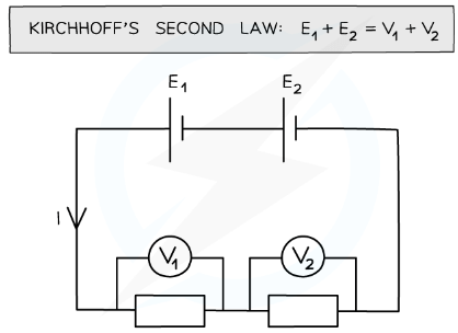 The sum of the voltages are equal to the sum of the e.m.f from the batteries
- In a series circuit, the voltage is split across all components depending on their resistance
- The sum of the voltages is equal to the total e.m.f of the power supply
- In a parallel circuit, the voltage is the same across each closed loop
- The sum of the voltages in each closed circuit loop is equal to the total e.m.f of the power supply:
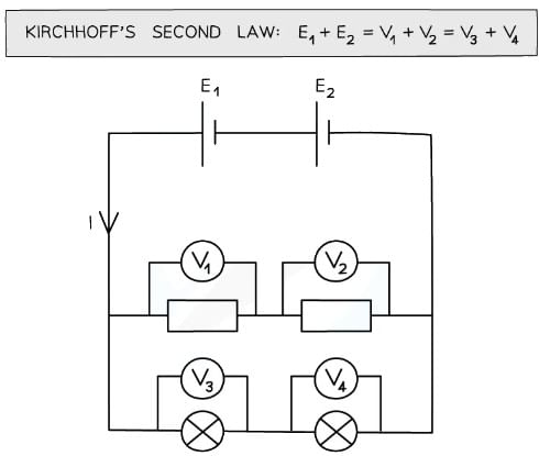
- A closed circuit loop acts as its own independent series circuit and each one separates at a junction
- A parallel circuit is made up of two or more of these loops
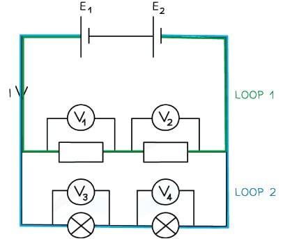 Each circuit loops acts as a separate, independent series circuit
- This is why parallel circuits are incredibly useful for home wiring systems
- A single power source supplies all lights and appliances with the same voltage
- If one light breaks, voltage and current can still flow through for the rest of the lights and appliances
Kirchhoff's First & Second Law in Circuits
- Kirchhoff’s laws can be used to solve simple circuit problems
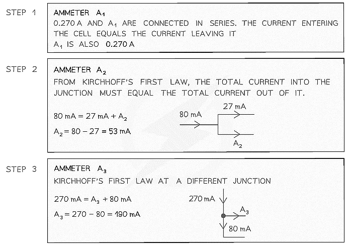
Using Kirchhoff's First Law
- Remember:
- The sum of the currents entering a junction always equal the sum of the currents out of the junction
Example: For the circuit below, state the readings of ammeters A1, A2 and A3.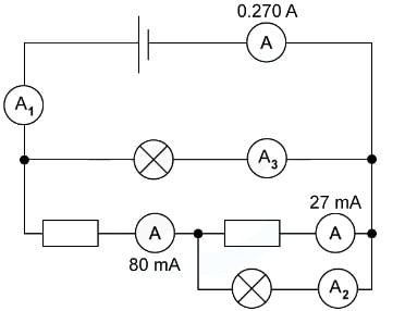
Using Kirchhoff's Second Law
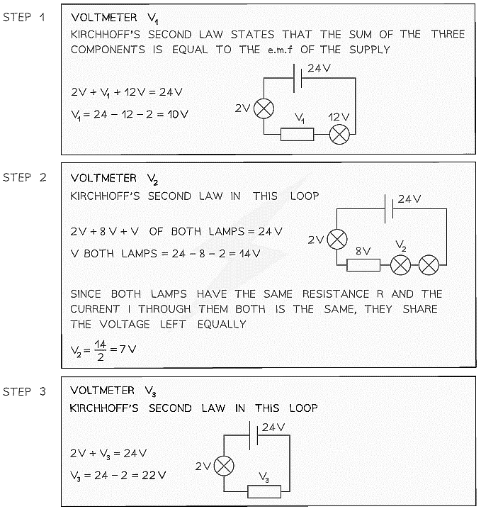
- Remember: The sum of the e.m.f’s in a closed circuit equals the sum of the potential differences
Example: For the circuit below, state the readings of the voltmeters V1, V2 and V3.All the lamps and resistors have the same resistance.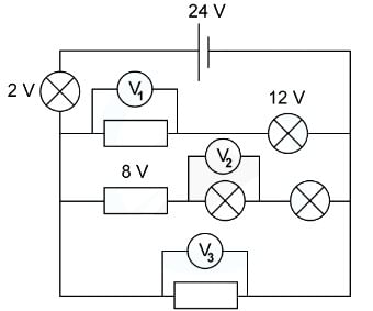
Resistors in Series & Parallel Circuits
Combining Resistors in Series
- When two or more components are connected in series:
- The combined resistance of the components is equal to the sum of individual resistances
- For example, for three resistors connected in series:
 Combined resistance of two or more resistors in series equation
Combined Resistance R = R1 + R2 + R3 ... In Series
Example: The combined resistance R in the following series circuit is 60 Ω.What is the resistance value of R2?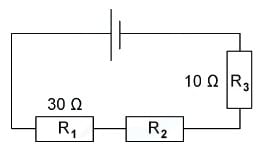
(a) 100 Ω
(b) 30 Ω
(c) 20 Ω
(d) 40 Ω
Step 1: Equation for Combined Resistance in Series R = R1 + R2 + R3
Step 2: Substitute In Values for Total Resistance R and The Other Resistors
60Ω = 30Ω + R2 + 10Ω
Step 3: Rearrange for R2
R2 = 60Ω - 30Ω - 10Ω
R2 = 20Ω
Combining Resistors in Parallel
When two or more component are connected in parallel:
- The reciprocal of the combined resistance is the sum of the reciprocals of the individual resistances
Example, for two resistors connected in parallel: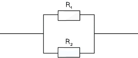 Combined resistance of two or more resistors in parallel equation
Combined Resistance in Parallel = 1/R = 1/R1 + 1/R2 + 1/R3 ...
- This means the combined resistance decreases and is less than the resistance of any of the individual components
- For example, If two resistors of equal resistance are connected in parallel, then the combined resistance will halve
Example: The circuit below shows 3 resistors connected in parallel.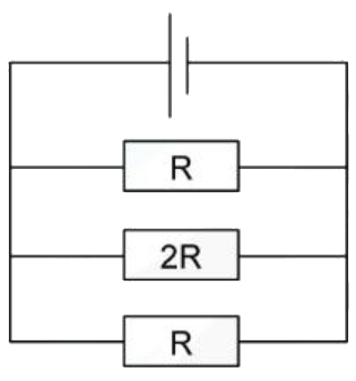
Which value gives the combined resistance of all the resistors in this circuit?
(a) 5R/A
(b) 2/5R
(c) 5/2R
(d) 2R/5
Ans. d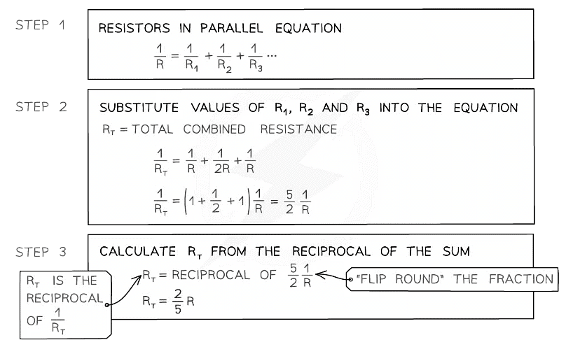
 |
Download the notes
Series & Parallel Circuits
|
Download as PDF |
Series & Parallel Circuits
Analysing Series & Parallel Circuits
Current
- In a series circuit, the current is the same for all components
- In a parallel circuit, the current is split across the different branches (or junction). The total current into a junction must equal the total current out of a junction
- The amount of current in each branch depends on the total resistance of the components within that branch
Potential Difference
- In a series circuit, the e.m.f of the power supply is shared amongst all the components in different amounts, depending on their resistance
- In a parallel circuit, the voltage of all the components in each branch is equal to the e.m.f of the power supply
Summary
- A summary of the current, voltage and resistance within a series and parallel circuit are summarised below:
Table of Voltage, Current & Resistance in Series & Parallel Circuits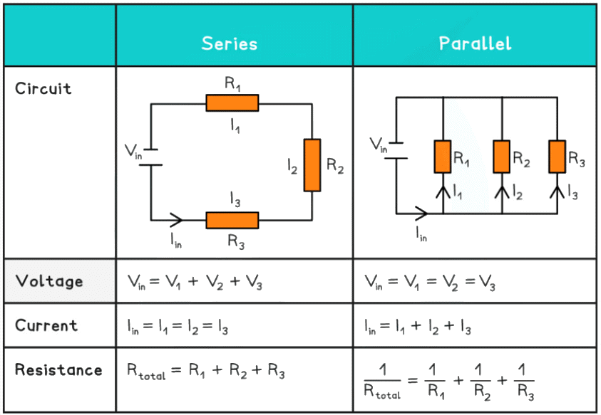
Circuits with Multiple Sources of E.M.F
- More complex circuit problems may include circuits with two or more sources of e.m.f
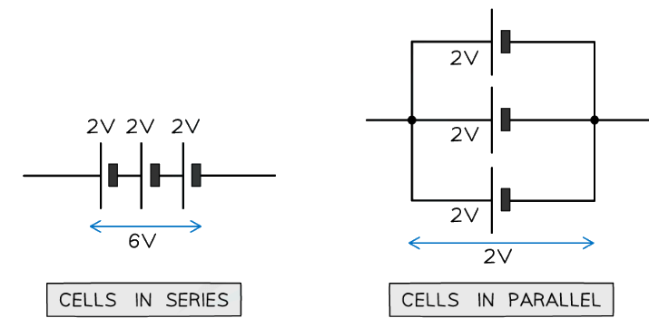
This is often from multiple cells - Cells can also be connected in series or parallel
- The total voltage of the combined cells can be calculated in the same way as voltage
- If the cells are connected in series, the total voltage between the ends of the chain of cells is the sum of the potential difference across each cell
- If the cells are connected in parallel, the total voltage across the arrangement is the same as for one cell
- The important part is making sure current flowing in one direction (from positive to negative) is taken as positive and the current flowing in the opposite direction as negative
Aims of the Experiment
- The aim of the experiment is to investigate circuits with more than one source of e.m.f (batteries)
- The total potential difference measured in a series and parallel circuit should be similar to the calculated total potential difference of the circuit
Variables:
- Independent variable = Potential difference of the cells, Vtotal
- Dependent variable = Potential difference of the resistor, V
Equipment List
- Cells
- Leads
- Voltmeter
- Resistor
- Resolution of measuring equipment: Voltmeter = 0.1 V
Method
- Set up a circuit with two cells in series. They can be of any voltage but preferably low (eg. 5 V) with a fixed resistor. Connect a voltmeter around the resistor
- Record the voltage across the resistor, as the resistor is the only
- component this will be the potential difference supplied by the cells
- Swap at least one of the cells to one with a higher voltage
- Record the reading on the voltmeter again
- Repeat this for 3-5 voltage readings for the resistor
- Set up a circuit now with the two cells in parallel. Still, connect a voltmeter around the resistor
- Record the voltage across the resistor
- Replace the batteries with two batteries with a different voltage, still in parallel. They both must have the same voltage
- Repeat the experiment for 3-5 voltage readings for the resistor
Analysis of Results
- The expected combined potential difference (p.d) for each battery combination is calculated by the following:
- In series: Combined p.d is the sum of their individual voltages
Vtotal = V1 + V2 + ... Vn for n sources of e.m.f - In parallel: Combined p.d is the same as the p.d of each battery
- In series: Combined p.d is the sum of their individual voltages
- Compare the results of the p.d across the resistor to its expected combined p.d
- In parallel, the resistor will have the same p.d as the batteries because their terminals are at the same point. Therefore, the potential between those two points are still the same
- The 2 batteries connected in parallel should not be different voltages
- The one with the higher voltage will discharge into the one of lower until they are equal which can cause wires to be burnt, creating sparks when connecting the cells
- This can cause overheating and failure of both batteries
Evaluating the Experiment
Systematic Errors
- Make sure the voltmeter starts from 0, to avoid a zero error
Random Errors
- The internal resistance of the cells will affect the reading on the voltmeter, so the p.d calculated may not be exactly as predicted
- If the circuit is not disconnected between each reading, the resistance of the components could be affected by the temperature rise in the components
- Repeat readings over a wide range of voltages will produce a more reliable result
Safety Considerations
- When there is a high current, and a thin wire, the wire will become very hot. Make sure never to touch the wire directly when the circuit is switched on
- Switch off the power supply right away if you smell burning
- Make sure there are no liquids close to the equipment, as this could damage the electrical equipment
- The components will get hot especially at higher voltages. Be careful when
- handling them
- Disconnect the power supply in between readings to avoid the components heating up too much
|
143 videos|360 docs|145 tests
|


