Potential Dividers | Physics for Grade 12 PDF Download
Introduction
- When two resistors are connected in series, through Kirchhoff’s Second Law, the potential difference across the power source is divided between them
- Potential dividers are circuits that produce an output voltage as a fraction of its input voltage
- This is done by using two resistors in series to split or divide the voltage of the supply in a chosen ratio
- Potential dividers have two main purposes:
- To provide a variable potential difference
- To enable a specific potential difference to be chosen
- To split the potential difference of a power source between two or more components
- Potential dividers are used widely in volume controls and sensory circuits using LDRs and thermistors
The Potentiometer
- A potentiometer is similar to a variable resistor connected as a potential divider to give a continuously variable output voltage
- It can be used as a means of comparing potential differences in different parts of the circuit
- The circuit symbol is recognised by an arrow next to the resistor, as shown below:
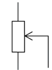
- A potentiometer is a single component that (in its simplest form) consists of a coil of wire with a sliding contact, midway along it
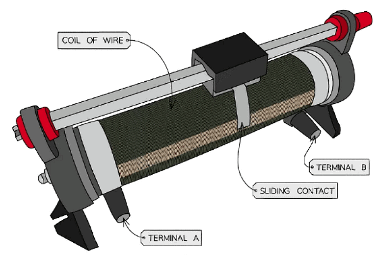
A potentiometer is a type of variable resistor
- It is recognised on a circuit diagram with a resistor fitted with a sliding contact
- The sliding contact has the effect of separating the potentiometer into two parts (an upper part and a lower part), both of which have different resistances
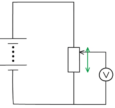
Moving the slider (the arrow in the diagram) changes the resistance (and hence potential difference) of the upper and lower parts of the potentiometer
- If the slider in the above diagram is moved upwards, the resistance of the lower part will increase and so the potential difference across it will also increase
- Therefore, the variable resistor obtains a maximum or minimum value for the output voltage
- If the resistance is 3 Ω:
- Maximum voltage is when the resistance is 3 Ω
- Minimum voltage is when the resistance is 0 Ω
Potential Divider Equations
- Since potential divider circuits are based on the ratio of voltage between components, this is equal to the ratio of the resistances of the resistors
- This is shown in the diagram and equation below:
Potential divider equation:
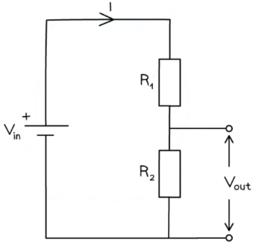
Potential divider diagram and equation
- The input voltage Vin is applied to the top and bottom of the series resistors
- The output voltage Vout is measured from the centre to the bottom of resistor R2
- The potential difference V across each resistor depends upon its resistance R:
- The resistor with the largest resistance will have a greater potential difference than the other one from V = IR
- If the resistance of one of the resistors is increased, it will get a greater share of the potential difference, whilst the other resistor will get a smaller share
- In potential divider circuits, the p.d across a component is proportional to its resistance from V = IR
- Another potential divider equation is one written as a ratio of the potential difference and resistances:

- Where:
- V1 = potential difference of R1 (V)
- V2 = potential difference or R2 (V)
- Using Ohm's Law, these can also be written as:
- V1 = IR1
- V2 = IR2
- Where I is the current through the circuit
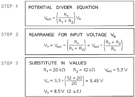
Example: The circuit is designed to light up a lamp when the input voltage exceeds a preset value.
It does this by comparing Vout with a fixed reference voltage of 5.3 V.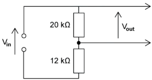
Vout is equal to 5.3
Calculate the input voltage Vin.
Example: A potential divider circuit consists of fixed resistors of resistance 5.0 Ω and 7.0 Ω connected in series with a 6.0 Ω resistor fitted with a sliding contact. These are connected across a battery of e.m.f 12 V and zero internal resistance, as shown.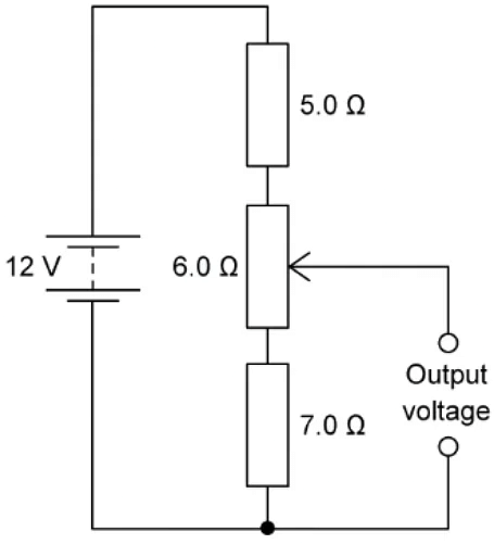
What are the maximum and minimum output voltages of this potential divider circuit?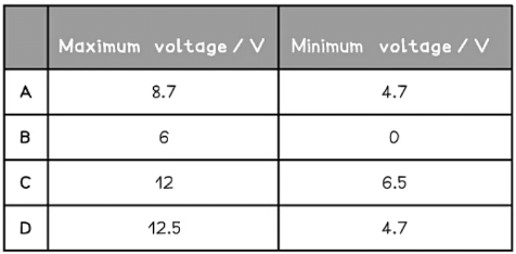
Ans. a
The potential difference at the top of the circuit (+ terminal) is 12v. at the bottom of the circuit (— terminal) is 0 v.
Potential divider equation for 3 resistorsmaximum output voltage the output voltage is maximum at the max value of the variable resistor = 6.0 Ω
Maximum output voltage =minimum output voltage the output voltage is minimum at the min value of the variable resistor = 0 Ω
Minimum output voltage =
Variable Resistance Components
- Variable and sensory resistors are used in potential dividers to vary the output voltage
- This could cause an external component to switch on or off e.g. a heater switching off automatically when its surroundings are at room temperature
- Sensory resistors used are light dependent resistors (LDRs) and thermistors
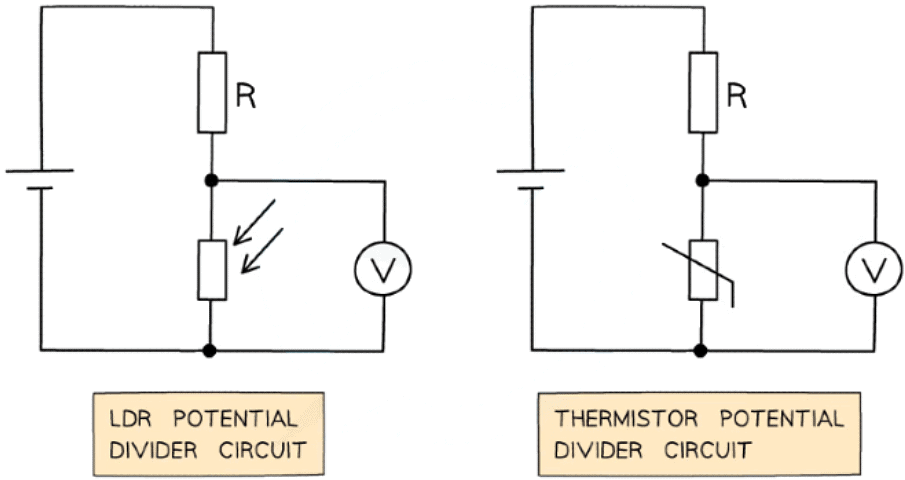
LDR and thermistor in a potential divider circuit with a fixed resistor R
- The voltmeter in both circuits is measuring Vout
- Recall that the resistance of an LDR varies with light intensity
- The higher the light intensity, the lower the resistance and vice versa
- An LDR circuit is often used for street and security lights
- The resistance of a thermistor varies with temperature
- The hotter the thermistor, the lower the resistance and vice versa
- A thermistor circuit is used in fire alarms, ovens and digital thermometers
- From Ohm’s law V = IR, the potential difference Vout from a sensory resistor in a potential divider circuit is proportional to its resistance
- If an LDR or thermistor's resistance decreases, the potential difference through it also decreases
- If an LDR or thermistor's resistance increases, the potential difference through it also increases
- Since the total p.d of the components must be equal to Vin, if the p.d of the sensory resistor decreases then the p.d of the other resistor in the circuit must increase and vice versa
Example: A potential divider consists of a fixed resistor R and a thermistor.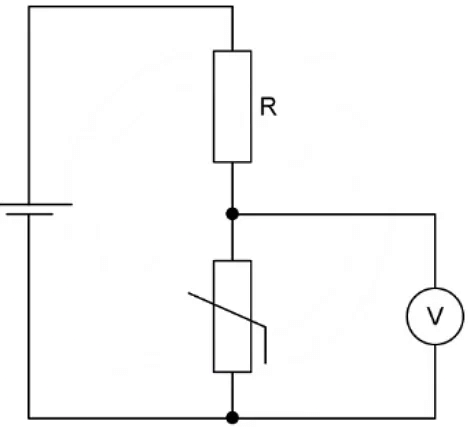
What happens to the p.d through resistor R and the thermistor when the temperature of the thermistor decreases?
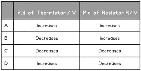
Ans: d
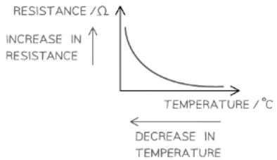
As the temperature of a thermistor decreases, its resistance increases resistance its increase in resistance
- Due to Ohm’s Law (V = IR), both the resistor and thermistor are connected in series and have the same current I
- If resistance R increases, the potential difference across the thermistor also increases
- In series, the potential difference is shared equally amongst the components. Their sum equals the e.m.f of the supply (Kirchhoff’s second law)
- If the potential difference across the thermistor increases, the potential difference across the resistance R must decreases, to keep the same overall total e.m.f
- This is row D
Investigating Potential Divider Circuits
Aims of the Experiment
The overall aim of the experiment is to calibrate a potential divider circuit for use as a light meter using an LDRVariables
- Independent variable = Light intensity (Lux)
- Dependent variable = Potential difference, V (V)
- Control variables:
- E.m.f of the power supply
Equipment List
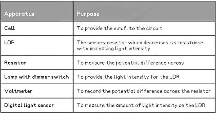
- Resolution of measuring equipment:
- Voltmeter = 1 mV
- Digital light sensor = 0.1 Lux
Method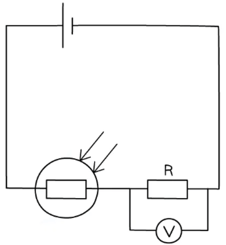
- Set up the circuit with the LDR and resistor R in series
- Record the value of the light intensity using the digital light sensor in a completely dark room
- Record the voltage across the resistor for this light intensity from the voltmeter
- Using the lamp with a dimmer switch, increase the light intensity slightly and record the new value recorded by the sensor
- Record the voltage across the resistor again with this new light intensity
- Repeat this process until the light intensity from the lamp cannot be increased any further
Analysing the Results
- Plot a graph of potential difference V across the resistor against the light intensity and draw a line of best fit
- This can be used as a calibration curve
- Move the circuit to an area of unknown light intensity and record the voltage across the resistor
- Using the calibration curve, find the corresponding light intensity to a particular potential difference
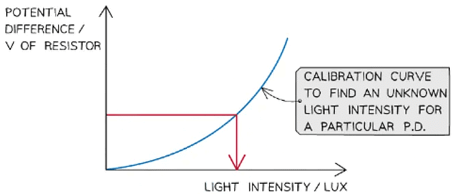
LDR calibration curve
- The resistance of the LDR and thermistor decreases with the increase in light intensity and temperature respectively
- Ohm’s Law states that the current between two points is directly proportional to the potential difference across those points
- Since R = V / I, this means the resistance between those points is constant, and a non-ohmic device doesn’t obey ohm’s law
- The potential difference provided by the cell is shared between the resistor and the non-ohmic device (the LDR)
- Therefore, a greater proportion of the voltage is shared across the resistor as the resistance of the non-ohmic device decreases
Investigating a Thermistor Circuit
Aims of the Experiment
- The overall aim of the experiment is to calibrate a potential divider circuit using a thermistor to find an unknown temperatureVariables
- Independent variable = Temperature, θ (°C)
- Dependent variable = Potential difference, V (V)
- Control variables:
E.m.f of the power supply
Equipment List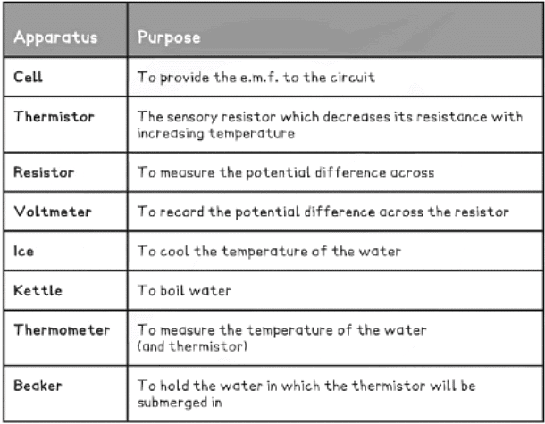
- Resolution of measuring equipment:
- Voltmeter = 1 mV
- Thermometer = 1 ºC
Method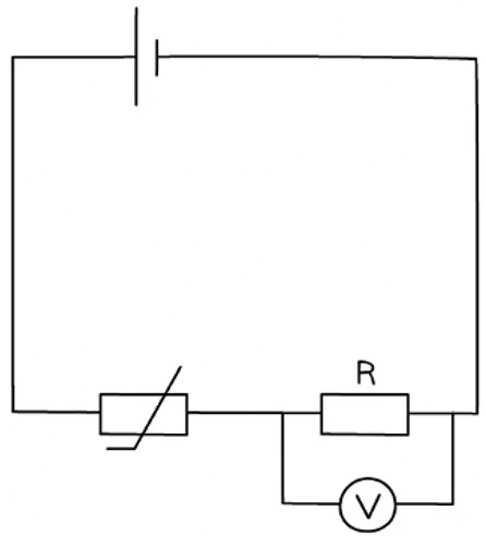
Thermistor circuit apparatus
- Replace the LDR in the circuit with a waterproof thermistor. Rather than light intensity being altered, it is now the temperature that must be altered
- Begin by placing the thermistor in a beaker filled with boiling water from the kettle
- Record the potential difference across the resistor as before, taking readings of the voltage for every 5°C decrease
- As the temperature falls to room temperature, place ice in the beaker to further lower the temperature as much as possible
Analysing the Results
- Similar to the LDR, plot a graph of potential difference (V) against temperature (in C) and draw a line of best fit
- Using the calibration curve, find the corresponding temperature to a particular potential difference
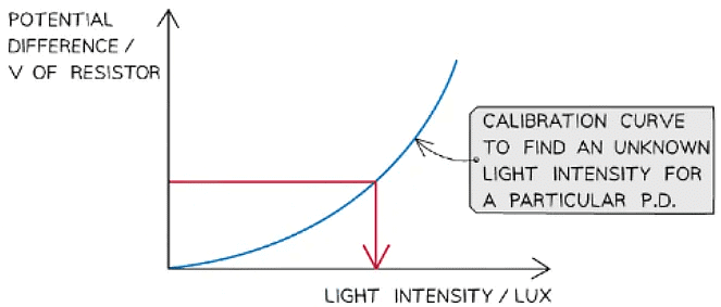
Thermistor calibration curve
Evaluating the Experiment
- Systematic Errors: Make sure the voltmeter and digital light sensor start at 0 to avoid a zero error
- Random Errors: Repeating measurements for the potential difference will reduce random errors
- To increase the accuracy of the calibration curve, take as many readings as possible over a wide range so that there are as many data points as possible
- The temperature of the thermistor is assumed to be the same as the temperature of the water
Make sure the water is stirred thoroughly to make sure its temperature is even
Safety Considerations
- This is a very safe experiment, however, electrical components can get hot when used for a long period
- Switch off the power supply right away if burning is smelled
- Make sure there are no liquids close to the equipment, as this could damage the electrical equipment
- Be careful not to be scalded by boiling water by not letting it splash
- Since the lamp can become very bright, do not look directly into it as this will damage your vision
- Be careful not to trip when the room is dark. Keep all belongings under desks to avoid this
|
163 videos|434 docs|181 tests
|

