HC Verma Questions and Solutions: Chapter 32: Electric Current in Conductors- 2 | HC Verma Solutions - JEE PDF Download
Exercises
Q.1. The amount of charge that passes in time t through a cross-section of a wire is Q(t) = At2 + Bt + C.
(a) Write the dimensional formulae for A, B and C.
(b) If the numerical values of A, B and C are 5, 3 and 1, respectively, in S.I units, find the value of the current at t = 5 s.
(a) Amount of charge,
Q(t) = At2 + Bt + C
We can only add the terms with the same dimensions. So, all the individual terms will have dimensions equal to the dimensions of the charge.
Comparing the dimensions of each term separately, we get:-
where I = current through the wire
Now,
(b) Current I = rate of flow of charge
Q.2. An electron gun emits 2.0 ×10¹⁶ electrons per second. What electric current does this correspond to?
Rate of emission of electrons = 2 ×10¹⁶ per second
Total charge passing through the gun = 2 ×1016 ×1.6 × 10–19 = 3.2 × 10⁻³ per second
We know:-
Current, I = rate of flow of charge
∴ I = 3.2 × 10⁻³ A
Q.3. The electric current existing in a discharge tube is 2.0 μA. How much charge is transferred across a cross-section of the tube in 5 minutes?
Let Q amount of charge be transferred across the cross-section of the tube.
Given:-
Current through the discharge tube, I = 2 μA = 2 × 10⁻⁶ A
Time taken to transfer charge, t = 5 mins = 300 s
We know:-
Q = It
∴ Q = 2 × 10–6 × 300 = 6× 10⁻⁴ C
Q.4. The current through a wire depends on time as i = i0 + αt, where i0 = 10 A and α = 4 As–1. Find the charge that crosses through a section of the wire in 10 seconds.
Current through the wire varies with time as
i = i0 + α t
Time interval, t = 10 s
i0 = 10 A
α = 4 A/sec
We know that for variable current,
Q.5. A current of 1.0 A exists in a copper wire of cross-section 1.0 mm2. Assuming one free electron per atom, calculate the drift speed of the free electrons in the wire. The density of copper is 9000 kg m–3.
Given:-
Current, i = 1 A
Area of cross-section, A = 1 mm2 = 1 × 10⁻⁶ m2
Density of copper,
ρ = 9000 kg/m3
Length of the conductor = l
Also,
Mass of copper wire = Volume × density
We know that the number of atoms in molecular mass M = NA
∴ Number of atoms in mass m, N =
where NA is known as Avagadro's number and is equal to 6 × 10²³ atoms.
Also, it is given that
No. of free electrons = No. of atoms
Let n be the number of free electrons per unit volume
= 0.073 mm/s
Q.6. A wire of length 1 m and radius 0.1 mm has a resistance of 100 Ω. Find the resistivity of the material.
Let ρ be the resistivity of the wire.
Given:-
Length, l = 1 m
Radius, r = 0.1 × 10⁻³ m
Area, A = πr2
Resistance, R = 1000 Ω
We know:-
Q.7. A uniform wire of resistance 100 Ω is melted and recast as a wire whose length is double that of the original. What would be the resistance of the wire?
Let
Resistivity of the wire = ρ
Original length of the wire = l
New length of the wire = l'
Original area of the wire = A
New area of the wire = A'
Original resistance of the wire = R = 100 Ω
New resistance of the wire = R'
Given:-
l' = 2l
The volume of the wire remains constant. So,
We know:-
Q.8. Consider a wire of length 4 m and cross-sectional area 1 mm2 carrying a current of 2 A. If each cubic metre of the material contains 1029 free electrons, find the average time taken by an electron to cross the length of the wire.
Given:-
Current through the wire, i = 2 A
Length of the wire, l = 4 m
Area of cross section, A = 1 mm2 = 1 × 10⁻⁶ m2
Number of electrons per unit volume, n = 1029
We know:-
where Vd is the drift speed.
Let t be the time taken by an electron to cross the length of the wire.
Q.9. What length of a copper wire of cross-sectional area 0.01 mm2 will be needed to prepare a resistance of 1 kΩ? Resistivity of copper = 1.7 × 10⁻⁸ Ωm
Given:-
Resistivity of copper, ρcu = 1.7 × 10⁻⁸ Ωm
Area of cross-section, A = 0.01 mm2 = 0.01 × 10⁻⁶ m2
Required resistance, R = 1 kΩ = 103 Ω
Let l be the required length of the copper wire.
We know:-
Q.10. The following figure shows a conductor of length l with a circular cross-section. The radius of the cross-section varies linearly from a to b. The resistivity of the material is ρ. Assuming that b – a << l, find the resistance of the conductor.
Let us consider a small element strip of length dx at a distance x from one end, as shown below.
Let the resistance of the small element strip be dR. Let the radius at that point be c .
Then, the resistance of this small strip,
Differentiating w.r.t to x, we get:-
Substituting the value of dx in equation (1), we get:-
Integrating dR from a to b, we get:-
Q.11. A copper wire of radius 0.1 mm and resistance kΩ is connected across a power supply of 20 V. (a) How many electrons are transferred per second between the supply and the wire at one end? (b) Write down the current density in the wire.
Given:-
Radius of the wire, r = 0.1 mm = 10-4 m
Resistance, R = 1 kΩ = 103 Ω
Voltage across the ends of the wire, V = 20 V
(a) Let q be the charge transferred per second and n be the number of electrons transferred per second.
We know:-
Also,
q = ne
(b) Current density of a wire,
Q.12. Calculate the electric field in a copper wire of cross-sectional area 2.0 mm2 carrying a current of 1 A. The resistivity of copper = 1.7 × 10⁻⁸ Ω m
Given:-
Area of cross-section, A = 2 × 10⁻⁶ m2
Current through the wire, i = 1 A
Resistivity of copper, ρ = 1.7 × 10⁻⁸ Ωm
Resistance of a wire,
Also from Ohm's Law, voltage across a wire,
The electric field of the wire,
Q.13. A wire has a length of 2.0 m and a resistance of 5.0 Ω. Find the electric field existing inside the wire if it carries a current of 10 A.
Given:-
Length of the wire, l = 2 m
Resistance of the wire, R = 5 Ω
Current through the wire, i = 10 A
From Ohm's Law, the potential difference across the wire,
V = iR
∴ V= 10 × 5 = 50 V
Electric field,
Q.14. The resistance of an iron wire and a copper wire at 20°C are 3.9 Ω and 4.1 Ω, respectively. At what temperature will the resistance be equal? Temperature coefficient of resistivity for iron is 5.0 × 10⁻³ K–1 and for copper, it is 4.0 × 10⁻³ K–1. Neglect any thermal expansion.
Given:-
Resistance RFe of the iron wire at 20°C = 3.9 Ω
Resistance RCu of the copper wire at 20°C = 4.1 Ω
Temperature coefficient αFe for iron = 5.0 × 10⁻³ K–1
Temperature coefficient αCu for copper = 4.0 × 10⁻³ K–1
Let
The temperature at which the resistance be equal = T
Resistance of iron wire at T °C = RFe'
Resistance of copper wire at T °C = RCu'
We know:-
⇒ T = 84.5°C
Q.15. The current in a conductor and the potential difference across its ends are measured by an ammeter and a voltmeter. The meters draw negligible currents. The ammeter is accurate but the voltmeter has a zero error (that is, it does not read zero when no potential difference is applied). Calculate the zero error if the readings for two different conditions are 1.75 A, 14.4 V and 2.75 A, 22.4 V.
Let the magnitude of zero error in the voltmeter reading be V.
We need to subtract the zero error from the readings obtained under the two given conditions to obtain the true value of potential difference.
Under both the conditions ,the resistance of the wire will not change.
Magnitude of zero error, V = 0.4 V, which can either be positive or negative. Positive or negative zero error just indicates that the needle of the voltmeter is to the right or left of the zero marked on the device if zero voltage is applied across the voltmeter.
Q.16. The following figure shows an arrangement to measure the emf ε and internal resistance r of a battery. The voltmeter has a very high resistance and the ammeter also has some resistance. The voltmeter reads 1.52 V when the switch S is open. When the switch is closed, the voltmeter reading drops to 1.45 V and the ammeter reads 1.0 A. Find the emf and the internal resistance of the battery.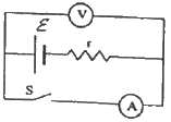
(a)
When the switch S is opened, loop 2 will be open and no current will pass through the ammeter. Loop 1 will be closed; so, a current will flow through it. But since the voltmeter has very high resistance, compared to the internal resistance of the battery, the voltage-drop across the internal resistance can be ignored, compared to the voltage drop across the voltmeter. So, the voltage appearing across the voltmeter will be almost equal to the emf of the battery.
∴ ε = 1.52 V
(b) When the switch is closed, current will pass through the circuit in loop 2. In this case, there will be a voltage drop across r due to current i flowing through it.
Applying the loop rule, we get:-
ε – ir = 1.45
⇒ 1.52 – ir = 1.45
⇒ ir = 0.07
⇒ 1.r = 0.07
r = 0.07 Ω
Q.17. The potential difference between the terminals of a battery of emf 6.0 V and internal resistance 1 Ω drops to 5.8 V when connected across an external resistor. Find the resistance of the external resistor.
Given:-
Emf of the battery, E = 6 V
Internal resistance, r = 1 Ω
Potential difference, V = 5.8 V
Let R be the resistance of the external resistor.
Applying KVL in the above circuit, we get:-
Also,
Q.18. The potential difference between the terminals of a 6.0 V battery is 7.2 V when it is being charged by a current of 2.0 A. What is the internal resistance of the battery?
Given:-
Potential difference across the terminals of the battery, V = 7.2 V
Emf of the battery, E = 6 V
Current flowing through the circuit, i = 2 A
As the battery is getting charged, the voltage drop across the terminals of the battery will be equal to the emf of the battery plus the voltage drop across the internal resistance of the battery.
So, V = E + ir
⇒ 7.2 = 6 + 2 × r
⇒ 1.2 = 2r
⇒ r = 0.6 Ω
Q.19. The internal resistance of an accumulator battery of emf 6 V is 10 Ω when it is fully discharged. As the battery gets charged up, its internal resistance decreases to 1 Ω.
The battery in its completely discharged state is connected to a charger that maintains a constant potential difference of 9 V. Find the current through the battery (a) just after the connections are made and (b) after a long time when it is completely charged.
(a) When the battery is being charged:-
Emf of the battery, E = 6 V
Internal resistance of the battery, r = 10 Ω
Potential difference, V = 9 V
Net e.m.f. across the resistance while charging = 9 – 6 = 3 V
(b) When the battery is completely charged:-
Internal resistance, r' = 1 Ω
Q.20. Find the value of i1/i2 in the following figure if (a) R = 0.1 Ω (b) R = 1 Ω and (c) R = 10 Ω. Note from your answers that in order to get more current from a combination of two batteries, they should be joined in parallel if the external resistance is small and in series if the external resistance is large, compared to the internal resistance.
(a) For R = 0.1 Ω
Applying KVL in the given circuit, we get:-
Now, consider the given circuit.
Applying KVL in the loop ABCDA, we get:-
Applying KVL in ADEFA, we get:-
(b) For R = 1 Ω
Applying KVL in the circuit given in figure 1, we get:-
Now, for figure 2:-
Applying KVL in ABCDA, we get:-
Applying KVL in ADEFA, we get:-
(c) For R = 10 Ω
Applying KVL in the circuit given in figure 1, we get:-
Now, for figure 2:-
Applying KVL in ABCDA, we get:-
Applying KVL in ADEFA, we get:-
Q.21. Consider N = n1n2 identical cells, each of emf ε and internal resistance r. Suppose n1 cells are joined in series to form a line and n2 such lines are connected in parallel.
The combination drives a current in an external resistance R. (a) Find the current in the external resistance. (b) Assuming that n1 and n2 can be continuously varied, find the relation between n1, n2, R and r for which the current in R is maximum.
(a)
Given:-
Emf of one cell = E
∴ Total e.m.f. of n1 cells in one row = n1E
Total emf of one row will be equal to the net emf across all the n2 rows because of parallel connection.
Total resistance in one row = n1r
Total resistance of n2 rows in parallel
Net resistance of the circuit =
(b) From (a),
For I to be maximum, (n1r + n2R) should be minimum
It is minimum when
∴ I is maximum when n1r = n2R .
Q.22. A battery of emf 100 V and a resistor of resistance 10 kΩ are joined in series. This system is used as a source to supply current to an external resistance R. If R is not greater than 100 Ω, the current through it is constant up to two significant digits.
Find its value. This is the basic principle of a constant-current source.
Given:-
Emf of the battery, E = 100 volt
Resistance in series with battery, R' = 10 kΩ = 10000 Ω
External resistance, R = (1-100) Ω
When no external resistor is present (R = 0), current through the circuit,
We can see that up to R = 100 Ω, the current does not change up to two significant digits.
Q.23. If the reading of the ammeter, A1 in the following figure is 2.4 A, what will be the readings of ammeters A2 and A3? Neglect the resistances of the ammeters.
Given: i1 = 2.4 A
Since the 20 Ω and 30 Ω resistors are connected in parallel, the voltage across them will be the same.
From the figure,
∴ The reading of ammeter A3 = i = 4 A
The reading of ammeter A2 = i - i1 = 1.6 A
Q.24. The resistance of the rheostat shown in the figure is 30 Ω. Neglecting the meter resistance, find the minimum and maximum currents through the ammeter as the rheostat is varied.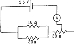
Current will be minimum when the rheostat will have maximum resistance, i.e 30 Ω.
In this case, total resistance of the circuit =
The minimum current through the circuit,
Current will be maximum when the rheostat will have minimum resistance, i.e. 0 Ω.
In this case, total resistance of the circuit =
The maximum current through the circuit,
Q.25. Three bulbs, each with a resistance of 180 Ω, are connected in parallel to an ideal battery of emf 60 V. Find the current delivered by the battery when (a) all the bulbs are switched on, (b) two of the bulbs are switched on and (c) only one bulb is switched on.
(a) When all the bulbs are switched on, we have a combination of three bulbs in parallel.
The effective resistance of the circuit,
The current delivered by the battery,
(b) When two of the bulbs are switched on, they are parallel to each other.
The effective resistance of the circuit,
The current delivered by the battery,
(c) When only one bulb is switched on, the effective resistance of the circuit,
The current delivered by the battery,
Q.26. Suppose you have three resistors of 20 Ω, 50 Ω and 100 Ω. What minimum and maximum resistance can you obtain from these resistors?
We can obtain maximum resistance when all the resistors are connected in series.
So, maximum resistance,
The minimum resistance will be obtained when all the resistors are connected in parallel
So, minimum resistance,
Q.27. A bulb is made using two filaments. A switch selects whether the filaments are used individually or in parallel. When used with a 15 V battery, the bulb can be operated at 5 W, 10 W or 15 W. What should be the resistances of the filaments?
We know:-
where R is the resistance, V is the voltage drop and P is the power on which the bulb is operated.
We can calculate the resistance of the bulb for the same V and different P.
The resistances of the bulb for three different powers are:-
When the two resistance are used in parallel, the equivalent resistance will be less than their individual resistance.
∴ The two resistance are 45 Ω and 22.5 Ω.
Q.28. The following figure shows a part of a circuit. If a current of 12 mA exists in the 5 kΩ resistor, find the currents in the other three resistors. What is the potential difference between the points A and B?
Let the current flowing through the resistors be marked as shown in the figure.
Given: i = 12 mA
The resistors of 20 kΩ and 10 kΩ are connected in parallel. So, the potential difference across their ends will be same, i.e.
∴ The current flowing through the 20 kΩ resistor = i1 = 4 mA
The current flowing through the 10 kΩ resistor = i - i1 = 8 mA
From the figure,
The current flowing through the 100 kΩ resistor = i = 12 mA
The equivalent resistance between the points A and B,
The potential difference V between the points A and B,
Q.29. An ideal battery sends a current of 5 A in a resistor. When another resistor of 10 Ω is connected in parallel, the current through the battery is increased to 6 A. Find the resistance of the first resistor.
Let the resistance of the first resistor be R.
If V is the potential difference across R, then the current through it,
Now, the other resistor of 10 Ω is connected in parallel with R.
It is given that the new value of current through the circuit, i' = 6 A
The effective resistance of the circuit, R' =
Since the potential difference is constant,
Q.30. Find the equivalent resistance of the network shown in the figure between the points a and b.
The simplified circuit can be drawn as shown below.
Equivalent resistance
Q.31. A wire of resistance 15.0 Ω is bent to form a regular hexagon ABCDEFA. Find the equivalent resistance of the loop between the points (a) A and B (b) A and C and (c) A and D.
(a)
From the figure, it can be seen that between points A and B, the resistance of the first side of the hexagon will be in parallel with the total resistance of the other five sides.
The resistance of the first side can be calculated as shown below.
Resistance of the first leg =
Total resistance of the 5 legs =
∴ The effective resistance between the points A and B,
(b) From the figure, it can be seen that between points A and C, the resistance of the first two sides of the hexagon will be in parallel with the total resistance of the other four sides.
Resistance of the two legs =
Total resistance of the four legs =
∴ The effective resistance between the points A and C,
(c) From the figure, it can be seen that between points A and D, the resistance of the first three sides of the hexagon will be in parallel with the total resistance of the other three sides.
Resistance of the three legs =
∴ The effective resistance between the points A and D,
Q.32. Consider the circuit shown in the figure. Find the current through the 10 Ω resistor when the switch S is (a) open (b) closed.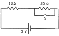
(a) When S is open, the resistors will be connected in series, as the current will flow through the 20 Ω resistor. The effective resistance,
The current flowing through the circuit,
(b) When S is closed, current will flow through the switch that offers the least resistive path. So, the 20 Ω resistance will be ineffective in this case. The effective resistance in this case,
The current flowing through the circuit,
Q.33. Find the currents through the three resistors shown in the figure.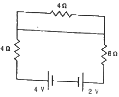
From the figure, we can see that current will flow only in loop 1 because current follows the least resistive path. All the current will pass through the wire connected in parallel to the 4 Ω resistor in loop 2.
∴ There will be no current through the 4 Ω resistor in loop 2.
For loop1, applying KVL, we get:-
∴ The current through the 4 Ω and 6 Ω resistors, i = 0.2 A
Q.34. The following figure shows a part of an electric circuit. The potentials at the points a, b and care 30 V, 12 V and 2 V respectively. Find the currents through the three resistors.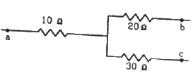
Let the potential at the point o be X volts.
From the figure,
Also, from kirchoff's junction law we have:-
i1 = i2 + i3
Thus, the currents through the three resistors are:-
Q.35. Each of the resistors shown in the figure has a resistance of 10 Ω and each of the batteries has an emf of 10 V. Find the currents flowing through the resistors a and bin the two circuits.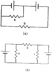
(a)
From the figure,
Potential difference between the two ends of resistor a = 10 V
Resistance of resistor a =10 Ω
∴ Current through a = 10/10 = 1A
Since the two batteries are connected opposite each other, potential difference between the terminals of b = 10 – 10 = 0 V
∴ Current through b = 0 A
(b)
From the figure,
Potential difference between the two ends of resistor a = 10 V.
Resistance of resistor a =10 Ω
∴ Current through a = 10/10 = 1A
Since the two batteries are again connected opposite to each other, Potential difference between terminal of b = 10 – 10 = 0 V
∴ Current through b = 0 A
Q.36. Find the potential difference Va – Vb in the circuits shown in the figure.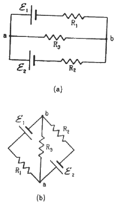
Applying KVL in loop 1, we get:-
Multiplying equation (1) by (R1+R3) and (2) by R3 and then subtracting (2) from (1), we get:-
Similarly, multiplying equation (1) by R3 and (2) by (R1+R3), and then subtracting (2) from (1), we get:-
(b) The circuit in figure b can be redrawn as shown below:-
We can see that it is similar to the circuit in figure a and, hence, the answer obtained will be same.
Q.37. In the circuit shown in the figure, ε1 = 3 V, ε2 = 2 V, εa = 1 V and r1 = r2 = r3 = 1Ω. Find the potential difference between the points A and B and the current through each branch.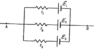
Applying KVL in loop 1, we get:-
Current through the top branch = i2 = 1 A
Current through the middle branch = i1 - i2 = 0 A
Current through the bottom branch = i1 = 1 A
Q.38. Find the current through the 10 Ω resistor shown in the figure.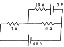
Applying KVL in loop 1, we get:-
3i + 6i1 = 4.5 ...............(1)
Applying KVL in loop 2, we get:-
Multiplying equation (1) by 10 and (2) by 3 and then, subtracting (2) from (1), we get:-
Substituting the value of i1 in (1), we get:-
So, current flowing through the 10 Ω resistor = i - i1 = 0.5 - 0.5 = 0 A
Q.39. Find the circuit in the three resistors shown in the figure.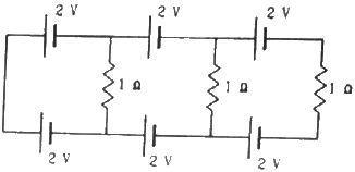
Applying KVL in loop 1, we get:-
Applying KVL in loop 2, we get:-
Applying KVL in loop 3, we get:-
Q.40. What should be the value of R in the figure for which the current in it is zero?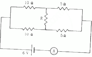
For current to be zero in the middle branch, the circuit should be balanced. According to the Wheatstone bridge principle, balancing a circuit does not depend on the value of resistance R in the middle branch. The circuit in this case is balanced. Hence, any value of R is acceptable.
Q.41. Find the equivalent resistance of the circuits shown in the figure between the points a and b. Each resistor has resistance r.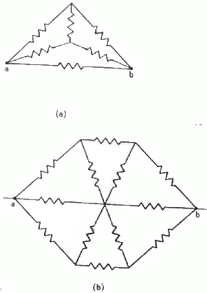
(a) The simplified circuit can be drawn as shown below.
Here cdeo forms a balanced Wheatstone bridge; therefore, branch od will become become ineffective.
The simplified circuit will then be as shown below.
The equivalent resistance between points c and e,
The equivalent resistance between a and b,
(b)
Let Reff be the effective resistance of the circuit. Then, from the symmetry of the circuit, we can assume that the current moving along CO enters OB and the current moving along EO enters OD.
Current on CO = current on OB
Current on EO = current on OD
So, the circuit can be simplified as shown below.
From the simplified circuit diagram, effective resistance of the upper half of the circuit will be
Q.42. Find the current measured by the ammeter in the circuit shown in the figure.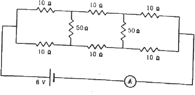
From the symmetry of the circuit,we can see that the potential at point C will be equal to the potential at point F. This implies that no current will flow in this branch. Hence, this arm of the circuit can be removed.
Similarly, the potential at point B will be equal to the potential at point G. So, this arm of the circuit can also be removed.
The simplified circuit diagram will be as shown below.
(b) From the figure, the effective resistance of the circuit,
The current through the circuit,
So, the ammeter reading will be 0.4 A.
|
136 docs
|

|
Explore Courses for JEE exam
|

|


