HC Verma Questions and Solutions: Chapter 34: Magnetic Field- 2 | HC Verma Solutions - JEE PDF Download
Exercises
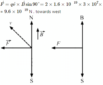
Q.1. An alpha particle is projected vertically upward with a speed of 3.0 × 10⁴ km s−1 in a region where a magnetic field of magnitude 1.0 T exists in the direction south to north. Find the magnetic force that acts on the α-particle.
Given:
Upward speed of the alpha particle, v = 3 × 10⁴ km/s = 3 × 10⁷ m/s
Magnetic field, B = 1.0 T
The direction of the magnetic field is from south to north.
Charge of the alpha particle, q = 2e,
where e is the charge of an electron.
q = 2 × 1.6 × 10−19 C,
Magnetic force acting on the α-particle,
The direction of magnetic force can be found using Fleming's left-hand rule.
Q.2. An electron is projected horizontally with a kinetic energy of 10 keV. A magnetic field of strength 1.0 × 10⁻⁷ T exists in the vertically upward direction.
(a) Will the electron deflect towards the right or left of its motion?
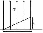
(b) Calculate the sideways deflection of the electron while travelling through 1 m. Make appropriate approximations.
Given:
The kinetic energy of the electron projected in the horizontal direction, K.E = 10 keV = 1.6 × 10⁻¹⁵ J
Magnetic field, B = 1 × 10⁻⁷ T
The direction of magnetic field is vertically upward.
(a) The direction can be found by the right-hand screw rule. So, the electron will be deflected towards left.
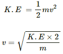
(b) Kinetic energy,
Magnetic force,
and F = ma
Therefore, equation (i) will be
Applying equation of motion
t= Time taken to cross the magnetic field
As there is no force acting on the electron in the horizontal direction, the velocity of the electron remain constant in this direction.
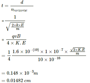
So, the time taken to cross a distance of 1m in the horizontal direction in the magnetic field,
s = 0.0148 = 1.5 × 10⁻² cm
Q.3. A magnetic field of  T exerts a force of
  on a particle with a charge of 1.0 × 10⁻⁹ C and going in the x − y plane. Find the velocity of the particle.
Given:-
Magnetic field, B =
Force exerted by the magnetic field on the charged particle, F =
Charge of the particle, q = 1 × 10⁻⁹ C
As per the question, the charge is going in the X-Y plane.
So, the x-component of force, Fx = 4 × 10⁻¹⁰ N
and the y-component of force, Fy = 3 × 10⁻¹⁰ N
Considering the motion along x-axis:-
Fx = qvy×B
On putting the respective values, we get:-
vy = 100 m/s
Motion along y-axis:-
Fy = qvx×B
⇒ vx = 75 m/s
Thus, total velocity =
Q.4. An experimenter's diary reads as follows: "A charged particle is projected in a magnetic field of  The acceleration of the particle is found to be
  The number to the left of i in the last expression was not readable. What can this number be?
Given,
Magnetic field, B = (7.0i − 3.0j) × 10−3 T
Acceleration of the particle, a = (xi + 7j) × 10−6 m/s2
We have denoted the unidentified number as x.
B and a are perpendicular to each other. (Because magnetic force always acts perpendicular to the motion of the particle)
So, the dot product of the two quantities should be zero.
That is, B.a = 0
⇒ 7x × 10−3 × 10⁻⁶ − 3 × 10−3 × 7 × 10−6 = 0
⇒ 7x − 21 = 0
x = 21/7 = 3
Acceleration of the particle is (3i + 7j) × 10−6 m/s2.
Q.5. A 10 g bullet with a charge of 4.00 μC is fired at a speed of 270 m s−1 in a horizontal direction. A vertical magnetic field of 500 µT exists in the space. Find the deflection of the bullet due to the magnetic field as it travels through 100 m. Make appropriate approximations.
Given:
Mass of the bullet, m = 10g
Charge of the bullet, q = 4.00 μC
Speed of the bullet in horizontal direction, v = 270 m/s
Vertical magnetic field, B = 500 μT
Distance travelled by the bullet, d = 100 m
Magnetic force,
Also,
F = ma
Using equation (i) we can write:
Time taken by the bullet to travel 100 m horizontally,
Deflection due to the magnetic field in this time interval,
= 3.7 × 10 -6 m.
Q.6. When a proton is released from rest in a room, it starts with an initial acceleration a0towards west. When it is projected towards north with a speed v0, it moves with an initial acceleration 3a0 towards west. Find the electric field and the maximum possible magnetic field in the room.
Given:
The initial acceleration of a proton, when it is released from rest, is a0 towards west.
F = qE ....(i)
F = ma0 ....(ii)
Here, q is the charge, E is the electric field and m is the mass.
On equating both the forces F of equations (i) and (ii), we get:
qE = ma0towards west
When the proton is projected towards north with a speed v0, it moves with an initial acceleration 3a0 towards west.
where B is the magnetic field.
Again, an electric force will act on the proton in the west direction, due to which, an acceleration a0 will act on the proton. Now, as the proton was initially moving with a velocity v, a magnetic force is also acting on the proton. So, the change in acceleration of the proton will be solely due to the magnetic force acting on it.
Change in acceleration towards west due to the magnetic force
= 3a0 − a0 = 2a0
So, F = m2a0
Hence, required magnetic field,
Q.7. Consider a 10-cm long portion of a straight wire carrying a current of 10 A placed in a magnetic field of 0.1 T making an angle of 53° with the wire. What magnetic force does the wire experience?
Given:
A straight wire of length, l = 10 cm
Electric current flowing through the wire, I = 10 A
Magnetic field, B = 0.1 T
Angle between the wire and magnetic field, θ = 53˚
Magnetic force,
⇒ F = 10 × 10 × 10-2 ×0.1 ×0.798
The direction of force can be found using Fleming's left-hand rule.
Therefore, the direction of magnetic force is perpendicular to the wire as well as the magnetic field.
Q.8. A current of 2 A enters at the corner d of a square frame abcd of side 20 cm and leaves at the opposite corner b. A magnetic field B = 0.1 T exists in the space in a direction perpendicular to the plane of the frame, as shown in the figure. Find the magnitude and direction of the magnetic forces on the four sides of the frame.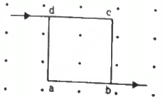
Given:
A square frame abcd of side, l = 20 cm
Electric current through the wire, I = 2 A
Magnetic field, B = 0.1 T
The direction of magnetic field is perpendicular to the plane of the frame, coming out of the plane.
As per the question, current enters at the corner d of the square frame and leaves at the opposite corner b.
Angle between the frame and magnetic field, θ = 90˚
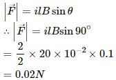
Magnetic force,
The direction of force can be found using Fleming's left-hand rule.
Thus, the direction of magnetic force is towards the left.
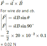
For wires dc and ab,
The direction of force can be found using Fleming's left-hand rule.
Thus, the direction of magnetic force is downwards.
Q.9. A magnetic field of strength 1.0 T is produced by a strong electromagnet in a cylindrical region of radius 4.0 cm, as shown in the figure. A wire, carrying a current of 2.0 A, is placed perpendicular to and intersecting the axis of the cylindrical region. Find the magnitude of the force acting on the wire.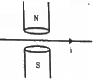
Given:
Magnetic field, (B) = 1 T
Radius of the cylindrical region, r = 4.0 cm
Electric current through the wire, I = 2 A
The direction of magnetic field is perpendicular to the plane of the wire.
So, angle between wire and magnetic field, θ = 90˚
Magnetic force,
= 2 × 8 ×10-2 × 1.0 × 1
= 0.16N
Q.10. A wire of length l carries a current i long the x-axis. A magnetic field exists, which is given as  T. Find the magnitude of the magnetic force acting on the wire.
Given:
A wire of length l cm
Electric current through the wire = i
Magnetic field,
As per the question, the current is passing along the X-axis.
Magnetic force,
Putting the repective values in the above equation, we get:
the magnitude of the magnetic force,
`therefore |vecF| = sqrt(2ilB_0
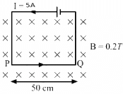
Q.11. A current of 5.0 A exists in the circuit shown in the figure. The wire PQ has a length of 50 cm and the magnetic field in which it is immersed has a magnitude of 0.20 T. Find the magnetic force acting on the wire PQ.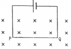
Given:
Length of the wire PQ inside the magnetic field, l = 50 cm
Electric current through the wire, I = 5 A
Magnetic field, B = 0.2 T
The direction of magnetic field is perpendicular to the plane of the frame and it is going into the plane of the circuit.
As per the question,
Angle between the plane of the wire and the magnetic field, θ = 90˚
Magnetic force,
= 5 × 50 × 10−2 × 0.2 × 1
= 0.50 N
The direction of force can be found using Fleming's left-hand rule.
Thus, the direction of magnetic force is upwards in the plane of the paper.
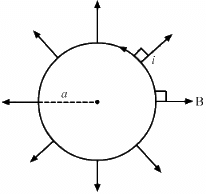
Q.12. A circular loop of radius a, carrying a current i, is placed in a two-dimensional magnetic field. The centre of the loop coincides with the centre of the field (figure). The strength of the magnetic field at the periphery of the loop is B. Find the magnetic force on the wire.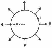
Given:-
A circular loop of radius = a
So, the length of the loop, l = 2πa
Electric current through the loop = i
As per the question,
The loop is placed in a two-dimensional magnetic field. The centre of the loop coincides with the centre of the field. The strength of the magnetic field at the periphery of the loop is B
Therefore, the magnetic field points radially outwards.
Here, the angle between the length of the loop and the magnetic field, θ = 90˚
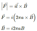
Magnetic force is given by
Direction of the force can be found using Fleming's left-hand rule.
Thus, the direction of magnetic force is perpendicular to the plane of the figure and pointing inside.
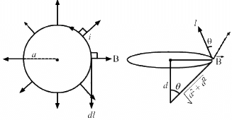
Q.13. A hypothetical magnetic field existing in a region is given by  denotes the unit vector along the radial direction. A circular loop of radius a, carrying a current i, is placed with its plane parallel to the x−y plane and the centre at (0, 0, d). Find the magnitude of the magnetic force acting on the loop.
Given:
A hypothetical magnetic field existing in a region,
where denotes the unit vector along the radial direction.
A circular loop of radius a
So, the length of the loop, l = 2πa
Electric current through loop = i
As per the question, the loop is placed with its plane parallel to the X−Y plane and its centre is at (0, 0, d).
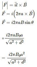
Here, angle between the length of the loop and the magnetic field is θ. Magnetic force is given by
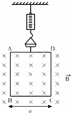
Q.14. A rectangular wire-loop of width a is suspended from the insulated pan of a spring balance, as shown in the figure. A current i exists in the anti-clockwise direction in the loop. A magnetic field B exists in the lower region. Find the change in the tension of the spring if the current in the loop is reversed.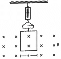
Given,
A rectangular wire loop of width a
Electric current through the loop = i
Direction of the current is anti-clockwise.
Strength of the magnetic field in the lower region = B
Direction of the magnetic field is into the plane of the loop.
Here, angle between the length of the loop and magnetic field, θ = 90˚
Magnetic force is given by
The magnetic force will act only on side AD and BC.
As side AD is outside the magnetic field, so F = 0
Magnetic force on side BC is
Direction of force can be found using Fleming's left-hand rule.
Thus, the direction of the magnetic force is upward.
Similarly if we change the direction of current to clockwise, the force along BC,
Thus, the change in force is equal to the change in tension = iaB − (− iaB) = 2iaB.
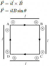
Q.15. A current loop of arbitrary shape lies in a uniform magnetic field B. Show that the net magnetic force acting on the loop is zero.
Given:
Uniform magnetic field existing in the region of the arbitrary loop = B
Let the electric current flowing through the loop be i.
Length of each side of the loop is l.
Assume that the direction of the current is clockwise.
Direction of the magnetic field is going into the plane of the loop.
Magnetic force is given by
Here, θ = 90˚
Direction of force can be found using Fleming's lef- hand rule.
Force F1 acting on AB = ilB upwards
Force F2 acting on DC = ilB downwards
So, F1 and F2 cancel each other.
Force F3 acting on AD = ilB outwards (Pointing towards the left from AB)
Force F4 acting on BC = ilB outwards (Pointing towards the right from BC)
So, F3 and F4 cancel each other.
Therefore, the net force acting on the arbitrary loop is 0.
Q.16. Prove that the force acting on a current-carrying wire, joining two fixed points a and b in a uniform magnetic field, is independent of the shape of the wire.
Given:
Uniform magnetic field existing in the region of the wire = B
Let the electric current flowing through the wire be i.
Length of the wire between two points a and b = l
Magnetic force is given by
Let us consider two wires of length l, one straight and the other circular.
The circular wire is of radius a such that 2πa = l
Suppose the magnetic field is pointing along the z direction and both the wires are lying in the xy plane, so that the angle between the area vector and the magnetic field is 90°.
For the straight wire of length l lying in a uniform magnetic field of strength B :
For the circular wire :
Angel between the area vector and magnetic field will again be 90°.
Force acting on the circular wire,
Both the forces are equal in magnitude. This implies that the magnetic force is independent of the shape of the wire and depends on the length and orientation of the wire.
Therefore, the magnetic force is independent of the shape of the wire.
Q.17. A semicircular wire of radius 5.0 cm carries a current of 5.0 A. A magnetic field B of magnitude 0.50 T exists along the perpendicular to the plane of the wire. Find the magnitude of the magnetic force acting on the wire.
Given,
Radius of semicircular wire, r = 5.0 cm
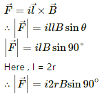
Thus, the length of the wire = 2r
Electric current flowing through wire = 5.0 A
Magnetic field, B = 0.50 T
Direction of magnetic field is perpendicular to the plane of the wire which implies that angle between length of the wire and magnetic field, θ = 90˚
As we know the magnetic force is given by
= 5 × 2 × 0.5 × =0.25 N
Q.18. A wire, carrying a current i, is kept in the x−y plane along the curve y = A sin  magnetic field B exists in the z direction. Find the magnitude of the magnetic force on the portion of the wire between x = 0 and x = λ.
Given:
Electric current flowing through the wire = i
The wire is kept in the x−y plane along the curve,
Magnetic field (B) exists in the z direction.
We have to find the magnetic force on the portion of the wire between x = 0 and x = λ.
Magnetic force is given by
For a small element dl,
The effective force on the whole wire is equivalent to the force on a starlight wire of length λ placed along the x axis.
So,
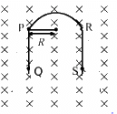
Q.19. A rigid wire consists of a semi-circular portion of radius R and two straight sections (figure). The wire is partially immersed in a perpendicular magnetic field B, as shown in the figure. Find the magnetic force on the wire if it carries a current i.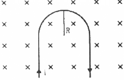
Given:-
Radius of the semi-circular portion of the rigid wire = R
Magnetic field = B
Electric current flowing through the wire = i
As per the question, the wire is partially immersed in a perpendicular magnetic field.
As PQ and RS are straight wires of length l each and strength of the magnetic field is also same on both the wires, the force acting on these wires will be equal in magnitude but their directions will be opposite to each other.(Direction of force can be found out using Fleming's left hand rule.)
So, the magnetic force on the wire PQ and the force on the wire RS are equal and opposite to each other. Both the forces cancel each other.
Therefore, only the semicircular loop PR will experience a net magnetic force.
Here, angle between the length of the wire and magnetic field, θ = 90˚
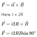
Magnetic force in the loop PR,
Q.20. A straight horizontal wire of mass 10 mg and length 1.0 m carries a current of 2.0 A. What minimum magnetic field B should be applied in the region, so that the magnetic force on the wire may balance its weight?
Given:
Mass of the wire, M = 10 mg = 10−5 Kg
Length of the wire, l = 1.0 m
Electric current flowing through wire, I = 2.0 A
As per the question, the weight of the wire should be balanced by the magnetic force acting on the wire.Also angle between the length of the wire and magnetic field is 90°
Thus, Mg = IlB, where g is the acceleration due to gravity = 9.8 m/s2
B is the applied magnetic field
So,
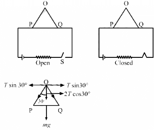
Q.21. Figure shows a rod PQ of length 20.0 cm and mass 200 g suspended through a fixed point O by two threads of lengths 20.0 cm each. A magnetic field of strength 0.500 T exists in the vicinity of the wire PQ, as shown in the figure. The wires connecting PQ with the battery are loose and exert no force on PQ. (a) Find the tension in the threads when the switch S is open. (b) A current of 2.0 A is established when the switch S is closed. Find the tension in the threads now.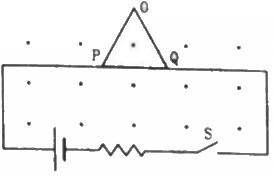
Given:
Length of the rod PQ = 20.0 cm
Mass of the rod, M = 200 g
Length of the two threads, l = 20.0 cm
Applied magnetic field, B = 0.500 T
As per the question,
(a) When the circuit is open:
The weight of the rod is balanced by the tension in the rod. So,
2Tcos30° = Mg
(b) When the circuit is closed and current flowing through the circuit = 2 A:
Then,
2Tcos 30°= Mg + ilB
= 0.200× 9.8 + 2 × 0.2 × 0.5
= 1.95 + 0.2 = 2.16
⇒ T = 1.245 = 1.25 N
Q.22. Two metal strips, each of length l, are clamped parallel to each other on a horizontal floor with a separation b between them. A wire of mass m lies on them perpendicularly, as shown in the figure. A vertically-upward magnetic field of strength B exists in the space. The metal strips are smooth but the coefficient of friction between the wire and the floor is µ. A current i is established when the switch S is closed at the instant t = 0. Discuss the motion of the wire after the switch is closed. How far away from the strips will the wire reach?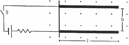
Given:-
Length of the two metal strips = l
Separation between the strips = b
Mass of the wire = m
Strength magnetic field = B
Coefficient of friction between the wire and the floor = µ
Let the distance covered by the wire be x.
Due to the presence of the magnetic field, a net magnetic force will act on the wire towards the right.
Let the wire has moved through a distance x after travelling the length of the strips.
As the contact between the wire and strip is smooth so coefficient of friction between them is zero. Under the influence of magnetic force,firstly the wire will travel a distance equal to the length of the strips. After this, it travels a distance x and also now,a frictional force will act on the wire in a direction opposite to its direction of motion.
So we can equate the work done by the magnetic force and the frictional force.
Thus, F × l = µmg × x,
where g is the acceleration due to gravity
⇒ ibBl = µmgx
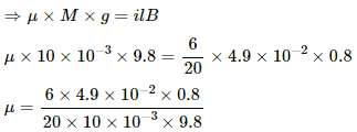
Q.23. A metal wire PQ of mass 10 g lies at rest on two horizontal metal rails separated by 4.90 cm (figure). A vertically-downward magnetic field of magnitude 0.800 T exists in the space. The resistance of the circuit is slowly decreased and it is found that when the resistance goes below 20.0 Ω, the wire PQ starts sliding on the rails. Find the coefficient of friction.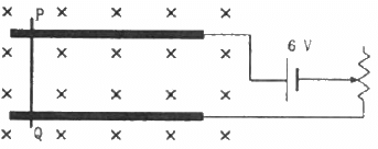
Given:-
Mass of the metal wire, M = 10 g
Distance between the two horizontal metal rails, l = 4.90 cm
Vertically-downward magnetic field, B = 0.800 T
As per the question, when the resistance of the circuit is slowly decreased below 20.0 Ω, the wire PQ starts sliding on the rails. At that moment, current in the wire,Using Fleming's left-hand rule, the magnetic force will act towards the right. So, due to this magnetic force, the wire will try to slide on the rails. The frictional force will try to oppose this motion of the wire.
When the wire just starts sliding on the rails, the frictional force acting on the wire will just balance the magnetic force acting on the wire. This implies
µR = F, where
µ is the coffiecent of friction
R is the normal reaction force and
F is the magnetic force
µ = 0.12
Q.24. A straight wire of length l can slide on two parallel plastic rails kept in a horizontal plane with a separation d. The coefficient of friction between the wire and the rails is µ. If the wire carries a current i, what minimum magnetic field should exist in the space in order to slide the wire on the rails?
Given:
Length of the wire = l
Distance between the plastic rails = d
The coefficient of friction between the wire and the rails = µ
Electric current flowing through the wire = i
The minimum magnetic field that should exist in the space, in order to slide the wire on the rails, should be such that the net magnetic force acting on the wire is equal to the frictional force on the wire.
µR = F,
where µ is the coefficient of friction between the wire and the rail R is the normal reaction force F is the magnetic force
µMg = iB
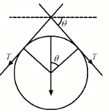
Q.25. The figure shows a circular wire loop of radius a and carrying a current i, which is placed in a perpendicular magnetic field B. (a) Consider a small part dl of the wire. Find the force on this part of the wire exerted by the magnetic field. (b) Find the force of compression in the wire.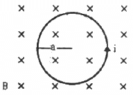
Given:-
Radius of the circular wire loop = a
Electric current flowing through the loop = i
Perpendicular magnetic field = B
(a) The force exerted by the magnetic field on a small element dl of the wire,
Fdl = i. (dl × B) = idlB
Using Fleming's left-hand rule, we can say that the direction of magnetic force is towards the centre for any small element of length dl of the wire (dl and B are perpendicular to each other).
(b) Suppose some part of wire loop subtends a small angle 2θ at the centre of a circular loop
So,
2Tsinθ = i.(dl × B)
= i.2aθ B (Using length of any arc, l =rθ)
∵ θ is very small, sinθ = θ
2Tθ = i.2aθB
∴ T = iaB
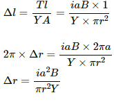
Q.26. Suppose that the radius of cross-section of the wire used in the previous problem is r. Find the increase in the radius of the loop if the magnetic field is switched off. Young's modulus of the material of the wire is Y.
Given:
Radius of cross-section of the wire = r
Young's modulus of the material of the wire is Y.
As per the question, when the applied magnetic field is switched off, the tension in the wire increased and so did its length.
Young's modulus,
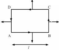
Here, T is the tension A is the area of cross-section Δl is the increse in length of the wire
Q.27. The magnetic field existing in a region is given by  A square loop of edge l and carrying a current i, is placed with its edges parallel to the x−y axes. Find the magnitude of the net magnetic force experienced by the loop.
Given:
Magnetic field,
Length of the edge of a square loop = l
Electric current flowing through it = i
As per the question, the loop is placed with its edges parallel to the X−Y axes.
In the figure, arrow denotes the direction of force on different sides of the square.
The net magnetic force experienced by the loop,
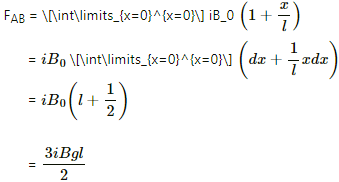
Force on AB:
Consider a small element of length dx at a distance x from the origin on line AB.
Force on this small element,
dF = iB_0 on the full length of AB,
Force on AB will be acting downwards.
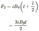
Similarly, force on CD,
Force on AB will be acting downwards.
Similarly, force on CD,
So, the net vertical force = F1 − F2 = 0
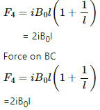
Force on AD,
So, the net horizontal force = F4−F3 = iB0l
Q.28. A conducting wire of length l, lying normal to a magnetic field B, moves with a velocity v,as shown in the figure. (a) Find the average magnetic force on a free electron of the wire. (b) Due to this magnetic force, electrons concentrate at one end, resulting in an electric field inside the wire. The redistribution stops when the electric force on the free electrons balances the magnetic force. Find the electric field developed inside the wire when the redistribution stops. (c) What potential difference is developed between the ends of the wire?
Given:-
Length of the conducting wire = l
Inward magnetic field = B
Velocity of the conducting wire = v
As the wire is moving with velocity v, we can consider this as the net motion of electrons inside the wire with velocity v.
(a) The average magnetic force on a free electron of the wire = e(v × B) = evB, where e is the charge of an electron.
(b) The redistribution stops when the electric force is just balanced by the magnetic force.
Electric force, F = eE and also magnetic force, F = evB
On equatinging the two forces, we get:-
eE = evB
⇒ E = vB
(c) The potential difference is developed between the ends of the wire:-
V = lE = lvB, where V is the potential difference across the ends of the wire.
Q.29. A current i is passed through a silver strip of width d and area of cross-section A. The number of free electrons per unit volume is n. (a) Find the drift velocity v of the electrons. (b) If a magnetic field B exists in the region, as shown in the figure, what is the average magnetic force on the free electrons? (c) Due to the magnetic force, the free electrons get accumulated on one side of the conductor along its length. This produces a transverse electric field in the conductor, which opposes the magnetic force on the electrons. Find the magnitude of the electric field which will stop further accumulation of electrons. (d) What will be the potential difference developed across the width of the conductor due to the electron-accumulation? The appearance of a transverse emf, when a current-carrying wire is placed in a magnetic field, is called Hall effect.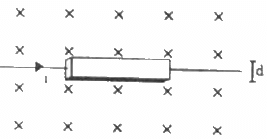
Given:-
Width of the silver strip = d
Area of cross-section = A
Electric current flowing through the strip = i
The number of free electrons per unit volume = n
(a) The relation between the drift velocity and current through any wire,
i = vnAe, where e = charge of an electron and v is the drift velocity.
(b)The magnetic field existing in the region is B.
The average magnetic force on a current-carrying conductor,
F = ilB
So, the force on a free electronupwards (Using Fleming's left-hand rule)
(c) Let us take the electric field as E.
So, further accumulation of electrons will stop when the electric force is just balanced by the magnetic force.
(d) The potential difference developed across the width of the conductor due to the electron-accumulation will be
V = Er
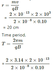
Q.30. A particle of charge 2.0 × 10⁻⁸ C and mass 2.0 × 10⁻¹⁰ g is projected with a speed of 2.0 × 10³ m s−1 in a region with a uniform magnetic field of 0.10 T. The velocity is perpendicular to the field. Find the radius of the circle formed by the particle and also the time period.
Given:
Charge of the particle, q = 2.0 × 10⁻⁸ C
Mass of the particle, m = 2.0 × 10⁻¹⁰ g
Projected speed of the particle, v = 2.0 × 10³ m s−1
Uniform magnetic field, B = 0.10 T.
As per the question, the velocity is perpendicular to the field.
So, for the particle to move in a circle, the centrifugal force to the particle will be provided by the magnetic force acting on it.
Using qvB = mv2/r, where r is the radius of the circle formed,
= 6.28 × 10⁻⁴ s
|
134 docs
|

