HC Verma Questions and Solutions: Chapter 38: Electromagnetic Induction- 5 | HC Verma Solutions - JEE PDF Download
Q.76. What are the values of the self-induced emf in the circuit of the previous problem at the times indicated therein?
Given:
Self-inductance, L = 1 H
For an inductor of self-inductance L, the emf induced is given by
(a) At t = 100 ms,
∴ Induced emf,
(b) At t = 200 ms,
∴ Induced emf
(c) At t = 1 s,
∴ Induced emf
Q.77. An inductor-coil of inductance 20 mH having resistance 10 Ω is joined to an ideal battery of emf 5.0 V. Find the rate of change of the induced emf at (a) t = 0, (b) t = 10 ms and (c) t = 1.0 s.
Given:
Self-inductance, L = 20 mH
Emf of the battery, e = 5.0 V
Resistance, R = 10 Ω
Now,
Time constant of the coil:
Steady-state current:
The current in the LR circuit at time t is given by
i = i0(1 − e−t/τ)
⇒ i = i0 − i0e−t/τ
On differentiating both sides, we get
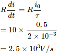
The rate of change of the induced emf is given by
(a) At time t = 0 s, the rate of change of the induced emf is given by
(b) At time t = 10 ms, the rate of change of the induced emf is given by
Now,
For t = 10 ms = 10 × 10−3 s = 10−2 s,
= 16.844 = 17 V/s
(c) At time t = 1 s, the rate of change of the induced emf is given by
= 0.00 V/s
Q.78. An LR circuit contains an inductor of 500 mH, a resistor of 25.0 Ω and an emf of 5.00 V in series. Find the potential difference across the resistor at t = (a) 20.0 ms, (b) 100 ms and (c) 1.00 s.
Given:
Inductance of the inductor, L = 500 mH
Resistance of the resistor connected, R = 25 Ω
Emf of the battery, E = 5 V
For the given circuit, the potential difference across the resistance is given by
V = iR
The current in the LR circuit at time t is given by
i = i0 (1 − e−tR/L)
∴ Potential difference across the resistance at time t, V = (i0(1 − e−tR/L)R
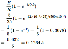
(a) For t = 20 ms,
i = i0(1 − e−tR/L)
Potential difference:
V = iR = (0.1264) × (25)
= 3.1606 V = 3.16 V
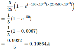
(b) For t = 100 ms,
i = i0(1 − e−tR/L)
Potential difference:
V = iR
= (0.19864) × (25) = 4.9665 = 4.97 V
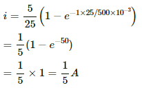
(c) For t = 1 s,
Potential difference:
V = iR
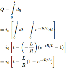
Q.79. An inductor-coil of resistance 10 Ω and inductance 120 mH is connected across a battery of emf 6 V and internal resistance 2 Ω. Find the charge which flows through the inductor in (a) 10 ms, (b) 20 ms and (c) 100 ms after the connections are made.
Given:
Inductance, L = 120 mH = 0.120 H
Resistance, R = 10 Ω
Emf of the battery, E = 6 V
Internal resistance of the battery, r = 2 Ω
The current at any instant in the LR circuit is given by
i = i0(1 − e−t/τ)
Charge dQ flown in time dt is given by
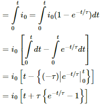
dQ = idt = i0(1 − e−t/τ)dt
Q = ∫ dQ
The steady-state current and the time constant for the given circuit are as follows:
Now,
(a) At time t = 0.01 s,
Q = 0.5 [0.01 + 0.01(e−0.1/0.01 − 0.01)]
= 0.00108 = 1.8 × 10−3 = 1.8 mΩ
(b) At t = 20 ms = 2 × 10⁻² s = 0.02 s,
Q = 0.5 [0.02 + 0.01(e−0.02/0.01 − 0.01)]
= 0.005676 = 5.7 × 10⁻³ C
= 5.7 mC(c) At t = 100 ms = 0.1 s,
Q = 0.5 [0.1 + 0.1 (e−0.1/0.01 − 0.01)]
= 0.045 C = 45 mc
Q.80. An inductor-coil of inductance 17 mH is constructed from a copper wire of length 100 m and cross-sectional area 1 mm2. Calculate the time constant of the circuit if this inductor is joined across an ideal battery. The resistivity of copper = 1.7 × 10⁻⁸ Ω-m.
Given:
Inductance, L = 17 mH
Length of the wire, l = 100 m
Cross-sectional area of the wire, A = 1 mm2 = 1 × 10⁻⁶ m2
Resistivity of copper, ρ = 1.7 × 10⁻⁸ Ω-m
Now,
The time constant of the L-R circuit is given by
Q.81. An LR circuit having a time constant of 50 ms is connected with an ideal battery of emf ε. find the time elapsed before (a) the current reaches half its maximum value, (b) the power dissipated in heat reaches half its maximum value and (c) the magnetic field energy stored in the circuit reaches half its maximum value.
Given:
Time constant of the LR circuit = 50 ms
Emf of the battery = ε
The time constant of the LR circuit is given by
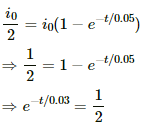
Let the current reach half of its maximum value in time t.
Now,
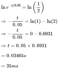
On taking natural logarithm (ln) on both sides, we get
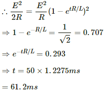
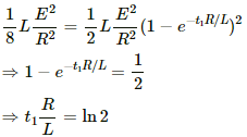
(b) Let t be the time at which the power dissipated is half its maximum value.
Maximum power = E2/R
(c) Current in the coil at the steady state,
Magnetic field energy stored at the steady state,
Half of the value of the steady-state energy =
Now,
= 0.061 s
= 61 ms
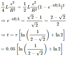
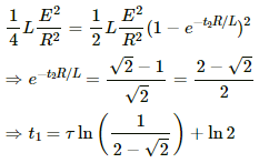
Q.82. A coil having an inductance L and a resistance R is connected to a battery of emf ε. Find the time taken for the magnetic energy stored in the circuit to change from one fourth of the steady-state value to half of the steady-state value.
Given:
Emf of the battery = ε
Inductance of the inductor = L
Resistance = R
Maximum current in the coil =
At the steady state, current in the coil,
The magnetic field energy stored at the steady state is given by
One-fourth of the steady-state value of the magnetic energy is given by
Half of the value of the steady-state energy =
Let the magnetic energy reach one-fourth of its steady-state value in time t1 and let it reach half of its value in time t2.
Now,
And,
Thus, the time taken by the magnetic energy stored in the circuit to change from one-fourth of its steady-state value to half of its steady-state value is given by
Q.83. A solenoid having inductance 4.0 H and resistance 10 Ω is connected to a 4.0 V battery at t = 0. Find (a) the time constant, (b) the time elapsed before the current reaches 0.63 of its steady-state value, (c) the power delivered by the battery at this instant and (d) the power dissipated in Joule heating at this instant.
Given:
Inductance, L = 4.0 H
Resistance, R = 10 Ω
Emf of the battery, E = 4 V
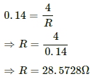
(a) Time constant
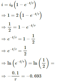
(b) As the current reaches 0.63 of its steady-state value, i = 0.63 i0.
Now,
0.63 i0 = i0(1 − e−t/τ)
⇒ e−t/τ = 1 − 0.063 = 0.37
⇒ ln e−t/τ = ln 0.37
⇒ t = 0.942 × 0.4
= 0.3977 = 0.4 s
(c) The current in the LR circuit at an instant is given by
i = i0(1 − e−t/τ)
= 0.4 × 0.6321
= 0.2528 A
Power delivered, P = Vi
⇒ P = 4 × 0.2528
= 1.01 = 1 W
(d) Power dissipated in Joule heating, P' = i2R
⇒ P' = (0.2258)2 × 10
= 0.639 = 0.64 W
Q.84. The magnetic field at a point inside a 2.0 mH inductor-coil becomes 0.80 of its maximum value in 20 µs when the inductor is joined to a battery. Find the resistance of the circuit.
Given:
Inductance of the inductor, L = 2.0 mH
Let the resistance in the circuit be R and the steady state value of the current be i0.
At time t , current i in the LR circuit is given by
i = i0(1 − e−t/τ)
Here,= Time constant
On multiplying both sides by µ0n, we get
n = Number of turns per unit length of the coil
µ0ni = µ0ni0(1 − e−t/τ)
⇒ B = B0(1 − e−tR/L)
⇒ 0.8 B0 = B0
⇒ 0.8 = (1 − e−R/100)
⇒ e−R/100 = 0.2
⇒ ln (e−R/100) = ln (0.2)
⇒ R = 169.3 Ω
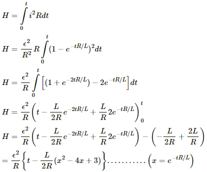
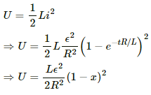
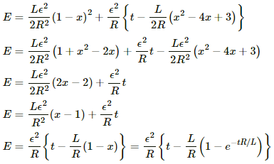
Q.85. An LR circuit with emf ε is connected at t = 0. (a) Find the charge Q which flows through the battery during 0 to t. (b) Calculate the work done by the battery during this period. (c) Find the heat developed during this period. (d) Find the magnetic field energy stored in the circuit at time t. (e) Verify that the results in the three parts above are consistent with energy conservation.
(a) Let the current in the LR circuit be i.
Let the charge flowing through the coil in the infinitesimal time dt be dq.
Now,
∴ dq = idt
The current in the LR circuit after t seconds after connecting the battery is given by
i = i0 (1 − e−t/τ)
Here,
i0 = Steady state current
τ = Time constant = L/R
dq = i0 (1 − e−tR/L) dt
On integrating both sides, we get
Thus, the charge flowing in the coil in time t is given by
(b) The work done by the battery is given by
W = εQ
From the above expression for the charge in the LR circuit, we have
(c) The heat developed in time t can be calculated as follows:
(d) The magnetic energy stored in the circuit is given by
(e) Taking the sum of total energy stored in the magnetic field and the heat developed in time t
The above expression is equal to the energy drawn from the battery. Therefore, the conservation of energy holds good.
Q.86. An inductor of inductance 2.00 H is joined in series with a resistor of resistance 200 Ω and a battery of emf 2.00 V. At t = 10 ms, find (a) the current in the circuit, (b) the power delivered by the battery, (c) the power dissipated in heating the resistor and (d) the rate at which energy is being stored in magnetic field.
Given:
Inductance of the inductor, L = 2 H
Resistance of the resistor connected to the inductor, R = 200 Ω,
Emf of the battery connected, E = 2 V
(a) The current in the LR circuit after t seconds after connecting the battery is given by
i = i0(1 − e−t/τ)
Here,
i0 = Steady state value of current
At time t = 10 ms, the current is given by
i = 0.01(1 − e−1)
i = 0.01(1 − 0.3678)
i = 0.01 × 0.632 = 6.3 mA
(b) The power delivered by the battery is given by
P = Vi
P = Ei0(1 − e−t/τ)
P = 0.02(1 − e−1)
P = 0.01264 = 12.6 mW
(c) The power dissipated in the resistor is given by
P1 = i2R
P1 = [i0(1 − e−t/τ)]2 R
P1 = (6.3 mA)2 × 200
P1 = 6.3 × 6.3 × 200 × 10−5
P1 = 79.38 × 10⁻⁴
P1 = 7.938 × 10−3 = 8 mW
(d) The rate at which the energy is stored in the magnetic field can be calculated as:
W = 2 × 10⁻²(0.225)
W = 0.455 × 10⁻²
W = 4.6 × 10⁻³
W = 4.6 mW
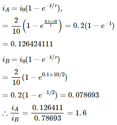
Q.87. Two coils A and B have inductances 1.0 H and 2.0 H respectively. The resistance of each coil is 10 Ω. Each coil is connected to an ideal battery of emf 2.0 V at t = 0. Let iA and iB be the currents in the two circuit at time t. Find the ratio iA / iB at (a) t = 100 ms, (b) t = 200 ms and (c) t = 1 s.
Given:
Inductance of the coil A, LA = 1.0 H
Inductance of the coil B, LB = 2.0 H
Resistance in each coil, R = 10 Ω
The current in the LR circuit after t seconds after connecting the battery is given by
i = i0 (1 − e−t/τ)
Here,
i0 = Steady state current
τ = Time constant = L/R
(a) At t = 0.1 s, time constants of the coils A and B are τA and τB, respectively.
Now,
Currents in the coils can be calculated as follows:
(b) At t = 200 ms = 0.2 s,
iA = 0.2 (1 − e−0.2 × 10.1)
iA = 0.2 × 0.864664716
iA = 0.1729329943
iB = 0.2 (1 − e−0.2 × 10.2)
iB = 0.2 × 0.632120 = 0.126424111
(c) At time t = 1 s,
iA = 0.2 (1 − e−1 × 10.1)
= 0.2 − 0.9999549
= 0.19999092
iB = 0.2 (1 − e−1 × 10.2)
= 0.2 × 0.99326 = 0.19865241
Q.88. The current in a discharging LR circuit without the battery drops from 2.0 A to 1.0 A in 0.10 s. (a) Find the time constant of the circuit. (b) If the inductance of the circuit 4.0 H, what is its resistance?
The current in the discharging LR circuit after t seconds is given by
i = i0 e−t/τ
Here,
i0 = Steady state current = 2 A
Now, let the time constant be τ.
In time t = 0.10 s, the current drops to 1 A.
The time constant is given by
(b) Given:
Inductance in the circuit, L = 4 H
Let the resistance in the circuit be R.
The time constant is given by
From the above relation, we have
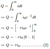
Q.89. A constant current exists in an inductor-coil connected to a battery. The coil is short-circuited and the battery is removed. Show that the charge flown through the coil after the short-circuiting is the same as that which flows in one time constant before the short-circuiting.
Consider an inductance L, a resitance R and a source of emf
are connected in series.
Time constant of this LR circuit is,
let a constant currentis maitened in the circuit before removal of the battery.
Charge flown in one time constant before the short-circuiting is,
Discahrge equation for LR circuit after short circuiting is given as,
Change flown from the inductor in small time dt after the short circuiting is given as,
dQ = idt
Chrage flown from the inductor after short circuting can be found by interating the above eqation within the proper limits of time,
Hence, proved.
Q.90. Consider the circuit shown in figure. (a) Find the current through the battery a long time after the switch S is closed. (b) Suppose the switch is again opened at t = 0. What is the time constant of the discharging circuit? (c) Find the current through the inductor after one time constant.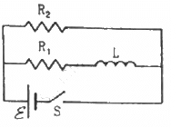
(a) Because the switch is closed, the battery gets connected across the L‒R circuit.
The current in the L‒R circuit after t seconds after connecting the battery is given by
i = i0 (1 − e−t/τ)
Here,
i0 = Steady state current
τ = Time constant = L/R
After a long time, t → ∞.
Now,
Current in the inductor, i = i0 (1 − e0) = 0
Thus, the effect of inductance vanishes.
(b) When the switch is opened, the resistance are in series.
The time constant is given by
(c) The inductor will discharge through resistors R1 and R2.
The current through the inductor after one time constant is given by
t = τ
∴ Current, i = i0 e−τ/τ
Here,
Q.91. A current of 1.0 A is established in a tightly wound solenoid of radius 2 cm having 1000 turns/metre. Find the magnetic energy stored in each metre of the solenoid.
Given:
Current through the solenoid, i = 1.0 A
Radius of the coil, r = 2 cm
Number of turns per metre, n = 1000
The magnetic energy density is given by
Volume of the solenoid, V = πr2l
For l = 1m, V = πr2
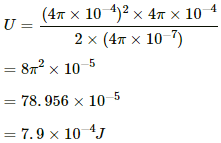
Thus, the magnetic energy stored in volume V is given by
The magnetic field is given by
B = μ0ni
= (4π × 10-7) × (1000) × 1
= 4π × 10-4 Τ
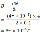
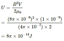
Q.92. Consider a small cube of volume 1 mm3 at the centre of a circular loop of radius 10 cm carrying a current of 4 A. Find the magnetic energy stored inside the cube.
Given:
Current in the loop, i = 4 A
Radius of the loop, r = 10 cm = 0.1 m
Volume of the cube, V = 1 mm3 = 1 × 10⁻⁹m
Magnetic field intensity at the centre of the circular loop:
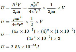
Magnetic energy density =Total energy stored in volume V:
Q.93. A long wire carries a current of 4.00 A. Find the energy stored in the magnetic field inside a volume of 1.00 mm3 at a distance of 10.0 cm from the wire.
Current flowing through the wire, i = 4.00 A
Volume of the region, V = 1 mm3
Distance of the region from the wire, d = 10 cm = 0.1 m
Magnetic field due to the current-carrying straight wire,
The magnetic energy stored is given by
Q.94. The mutual inductance between two coils is 2.5 H. If the current in one coil is changed at the rate of 1 As−1, what will be the emf induced in the other coil?
Given:
Mutual inductance between the coils, M = 2.5 H
Rate of change of current in one coil,
The flux in the coil due do another coil carrying current i is given by
ϕ = Mi
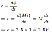
The emf induced in the second coil due to change in the current in the first coil is given by
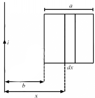
Q.95. Find the mutual inductance between the straight wire and the square loop of figure.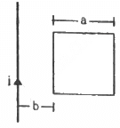
The flux through the square frame is given by
Let us first calculate the flux through the square frame.
Let us now consider an element of loop of length dx at a distance x from the wire.
Now,
Area of the element of loop, A = adx
Magnetic field at a distance x from the wire,
The magnetic flux of the element is given by
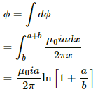
The total flux through the frame is given by
Also,
Thus, the mutual inductance is calculated as
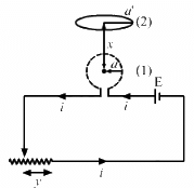
Q.96. Find the mutual inductance between the circular coil and the loop shown in figure.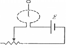
The magnetic field due to coil 1 at the centre of coil 2 is given by
The flux linked with coil 2 is given by
Now, let y be the distance of the sliding contact from its left end.
Given:
v = dy/dt
Total resistance of the rheostat = R
When the distance of the sliding contact from the left end is y, the resistance of the rheostat is given by r' = (R/L)y
The current in the coil is the function of distance y travelled by the sliding contact of the rheostat. It is given by
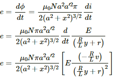
The magnitude of the emf induced can be calculated as:
emf induced,
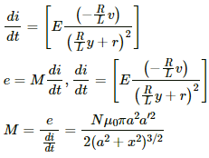
The emf induced in the coil can also be given as:
Q.97. A solenoid of length 20 cm, area of cross-section 4.0 cm2 and having 4000 turns is placed inside another solenoid of 2000 turns having a cross-sectional area 8.0 cm2 and length 10 cm. Find the mutual inductance between the solenoids.
Mutual inductance
M = μ0N1N2πr12l
= 4π × 10−7 × 4 × 103 × 2 × 103 × 4 × 10−4 × 10 × 10−2
= 0.04 × 10⁻² H
Given that,
For solenoid-1
Area of cross section, a1 = 4 cm2 = 4 × 10⁻⁴ m2
Length of the solenoid, l1 = 20 cm = 0.20 m
Number of turns per unit length , n1 = 4000/0.2 m = 20000 turns/m
For solenoid-2
Area of cross section, a2 = 8 cm2 = 4 × 10⁻⁴ m2
Length of the solenoid, l2 = 10 cm = 0.1 m
Number of turns per unit length, n2 = 2000/0.1 m = 20000 turns/m
It is given that the solenoid-1 is placed inside the solenoid-2
Let the current through the solenoid-2 be i.
The magnetic field due to current in solenoid-2
Now,
Flux through the coil-1 is given by
ϕ = n1l1.B.a1 = n1l1(μ0n2i) × a1
If the current flowing in the coil-2 changes, then emf is induced in the coil-1
Thus, emf induced in the coil-1 due to change in the current in coil-2 is given by
Q.98. The current in a long solenoid of radius R and having n turns per unit length is given by i = i0 sin ωt. A coil having N turns is wound around it near the centre. Find (a) the induced emf in the coil and (b) the mutual inductance between the solenoid ant the coil.
Given:
Radius of the long solenoid = R
Number of turns per unit length of the long solenoid = n
Current in the long solenoid, i = i0 sin ωt
Number of turns in the small solenoid = N
Radius of the small solenoid = R
The magnetic field inside the long solenoid is given by
B = μ0ni
Flux produced in the small solenoid because of the long solenoid, ϕ = (μ0ni) × (NπR2)
(a) The emf developed in the small solenoid is given by
Substituting i = i0 sin ωt, we get
e = μ0nNπR2i0ω cos ωt
(b) Let the mutual inductance of the coils be m.
Flux ϕ linked with the second coil is given by
ϕ = (μ0 ni) × (NπR2)
The flux can also be written as
ϕ = mi
∴ (μ0 ni) × (NπR2) = mi
And,
m = πμ0nNR2
|
134 docs
|


