Important Derivations: Electromagnetic Waves and Optical Instruments | Physics Class 12 - NEET PDF Download
| Table of contents |
|
| Important Derivations |
|
| Derivation of Lens Formula |
|
| Derivation of Prism Formula |
|
| Derivation Of Lens Maker Formula |
|
| Derivation of Mirror Formula |
|

Important Derivations
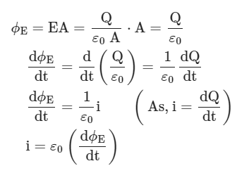
(1) Derive expression for displacement current
The electric flux between the plates of a capacitor is given by
 (2) Velocity of propagation of an electromagnetic wave
Derivation of Lens Formula
We know there are two types of lens: concave lens, and convex lens. These lenses are used as per the requirement and play an important role in the study of optics. Lens formula is a well-designed formula that is applicable for concave as well as convex lenses. The lens formula is used to find image distance, type of image formed, and the focal length (f). Let us know the derivation of the lens formula.
What is Lens Formula?
In optics, the relationship between the distance of the image (v), the distance of the object (u), and the focal length (f) of the lens is given by the formula known as the Lens formula. The Lens formula is applicable for convex as well as concave lenses. These lenses have negligible thickness. The formula is as follows:
Lens Formula Derivation
Consider a convex lens with an optical centre O. Let F be the principle focus and f be the focal length. An object AB is held perpendicular to the principal axis at a distance beyond the focal length of the lens. A real, inverted magnified image A’B’ is formed as shown in the figure.
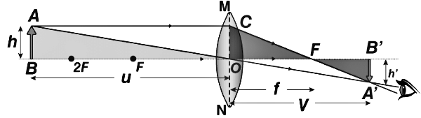
From the given figure, we notice that △ABO and △A’B’O are similar.
Therefore,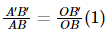
Similarly, △A’B’F and △OCF are similar, hence

But,
OC = AB
Hence,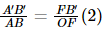
Equating eq (1) and (2), we get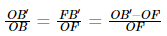
Substituting the sign convention, we get
OB=-u, OB’=v and OF=f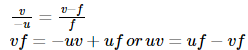
Dividing both the sides by uvf, we get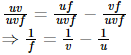
The above equation is known as the Lens formula.
Derivation of Prism Formula
Prism in Physics is defined as a transparent, polished flat optical element that reflects light. These can be made from any transparent material with wavelengths that they are designed for. The most commonly used material are glass, fluorite, and plastic.
Prisms called dispersive prisms are used to break the light into its spectral colours. Other uses of prisms are to split light into its components with the polarisation of light or to reflect light. Following are the types of prisms:
- Dispersive prisms: These are used to break the light into their constituent spectral colors. A triangular prism and amici prism grism are a few examples of dispersive prism.
- Reflective prisms: These are used to reflect light in order to invert, rotate, deviate or displace the light beam. Pentaprism, dove prism, and retroreflector prism are some examples of reflective prisms.
- Polarising prisms: These are used to split the beam of light by varying the polarization. Nicol prism and Glan-Taylor prism are some examples of polarising prisms.
- Beam-splitting prisms: These are used to split beams into two or more beams. Beam splitter cube and dichroic prism are examples of beam-splitting prism.
- Deflecting prisms: These are used to deflect the beam of light at a fixed angle. A wedge prism is an example of deflecting prism.
Derivation of prism formula
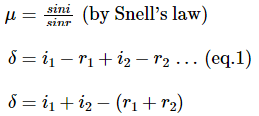
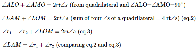
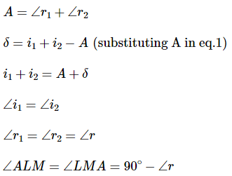
Thus, AL = LM and LM ∥ BC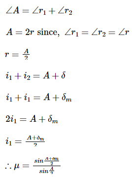
Thus, above is the prism formula.
Derivation Of Lens Maker Formula
Lenses of different focal lengths are used for various optical instruments. The lens’s focal length depends upon the refractive index of the material of the lens and the radii of curvatures of the two surfaces. The derivation of lens maker formula is provided here so that aspirants can understand the concept more effectively. Lens manufacturers commonly use the lens maker formula for manufacturing lenses of the desired focal length.
Lens Maker Formula Derivation
Assumptions
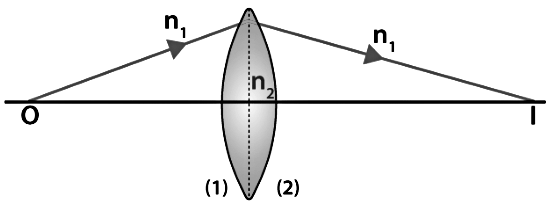
The following assumptions are taken for the derivation of lens maker formula.
- Let us consider the thin lens shown in the image above with 2 refracting surfaces having the radii of curvatures R1 and R2, respectively.
- Let the refractive indices of the surrounding medium and the lens material be n1 and n2, respectively.
Derivation
The complete derivation of the lens maker formula is described below. Using the formula for refraction at a single spherical surface, we can say that,
For the first surface,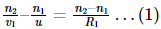
For the second surface,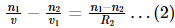
Now adding equation (1) and (2),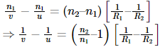
When u = ∞ and v = f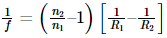
But also,
Therefore, we can say that,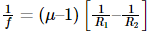
Where μ is the refractive index of the material.
Limitations of the lens maker’s formula
- The lens should not be thick so that the space between the 2 refracting surfaces can be small.
- The medium used on both sides of the lens should always be the same.
Derivation of Mirror Formula
The derivation of the mirror formula is one of the most common questions asked in various board examinations as well as competitive examinations. A mirror formula can be defined as the formula which gives the relationship between the distance of object ‘u’, the distance of image ‘v’, and the focal length of the mirror ‘f’. The mirror formula is applicable for both, plane mirrors and spherical mirrors (convex and concave mirrors). The mirror formula derivation is provided here so that students can understand the concept of the topic in a better way. The mirror formula is written as: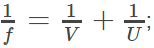
Assumptions for Derivation Of Mirror Formula
The following assumptions are taken in order to derive the mirror formula.
- The distances are being measured from the pole of the mirror.
- According to the convention, the negative sign indicates the distance measured in the direction opposite to the incident ray while the positive sign indicates the distance measured in the direction of the incident ray.
- The distance below the axis is negative whereas the distance above is positive.
Mirror Formula Derivation
The derivation of the mirror formula is given below. The diagram given below will help learners to understand the mirror formula derivation more effectively.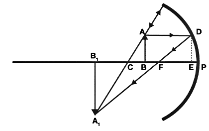
From the figure given above, it is obvious that the object AB is placed at a distance of U from P which is the pole of the mirror. From the diagram we can also say that the image A1B1 is formed at V from the mirror.
Now from the above diagram, it is clear that according to the law of vertically opposite angles the opposite angles are equal. So we can write:
∠ACB = ∠A1CB1;
Similarly;
∠ABC=∠A1B1C; (right angles)
Now since two angles of triangle ACB and A1CB1 are equal and hence the third angle is also equal and is given by;
∠BAC = ∠B1A1C; and
Similarly the triangle of FED and FA1B1 are also equal and similar, so;
Also since ED is equal to AB so we have;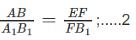
Combining 1 and 2 we have;
Consider that the point D is very close to P and hence EF = PF, so;
From the above diagram BC = PC - PB and B1C = PB1 - PC and FB1 = PB1 - PF;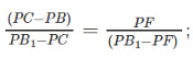
Now substituting the values of above segments along with the sign, we have;
PC = -R;
PB = u;
PB1 = -V;
PF = -f;
So the above equation becomes;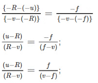
Solving it we have;
uv - uf - Rv + Rf = Rf - vf;
uv - uf - Rv + vf = 0;
since R = 2f (radius of curvature is twice that of focal length), hence;
uv - uf -2fv + vf = 0;
uv - uf - vf = 0;
Solving it further and dividing with "uv" we have;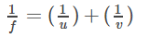
|
74 videos|314 docs|88 tests
|
FAQs on Important Derivations: Electromagnetic Waves and Optical Instruments - Physics Class 12 - NEET
| 1. What is the lens formula? |  |
| 2. How is the lens formula derived? | |
| 3. What is the prism formula? | |
| 4. How is the prism formula derived? | |
| 5. What are some applications of the lens and prism formulas? | |


Important Derivations: Electromagnetic Waves and Optical Instruments | Physics Class 12 - NEET
,Important Derivations: Electromagnetic Waves and Optical Instruments | Physics Class 12 - NEET
,video lectures
,Extra Questions
,Viva Questions
,Exam
,practice quizzes
,shortcuts and tricks
,Sample Paper
,Important Derivations: Electromagnetic Waves and Optical Instruments | Physics Class 12 - NEET
,MCQs
,mock tests for examination
,Semester Notes
,Free
,Important questions
,Previous Year Questions with Solutions
,study material
,past year papers
,ppt
,Summary
,Objective type Questions
;


Important Derivations: Electromagnetic Waves and Optical Instruments Free PDF Download
Importance of Important Derivations: Electromagnetic Waves and Optical Instruments
Important Derivations: Electromagnetic Waves and Optical Instruments Notes
Important Derivations: Electromagnetic Waves and Optical Instruments NEET Questions
Study Important Derivations: Electromagnetic Waves and Optical Instruments on the App
|
© EduRev
|
Education Revolution
|


|


