Best Study Material for Class 12 Exam
Class 12 Exam > Class 12 Notes > LCR Circuit: Series and Parallel
LCR Circuit: Series and Parallel - Class 12 PDF Download
An LCR circuit, also known as a resonant circuit, tuned circuit, or RLC circuit, is an electrical circuit consisting of an inductor (L), capacitor (C), and resistor (R) connected in series or parallel. In this document, we will study about LCR Circuit in detail.
Series LCR Circuit
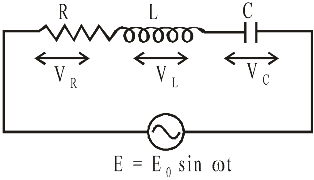 Series LCR Circuit
Consider a circuit containing a resistance R, inductance L, and capacitance C in series having an alternating emf
E = E0 sin ωt.
Let I be the current flowing in the circuit. VR, VL, and VC are respective potential differences across resistance R, inductance L, and capacitance C.
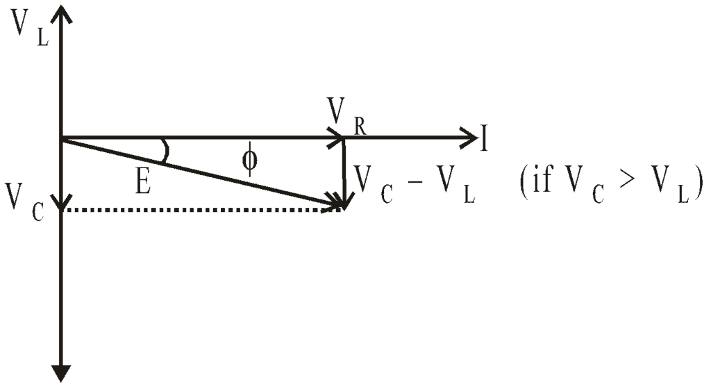 Phasor Diagram
The p.d. VR is in phase with current I. The p.d. VC lags behind the current by angle π/2. The p.d. VL leads the current by angle π/2.
∴ The resultant applied emf, 

i.e., 

∴ Impedance, 

The phase leads of current over applied emf is given by
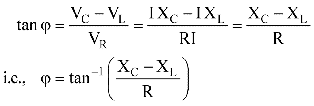
It is concluded that :
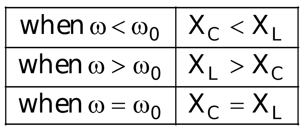
- If XC > XL, the value of φ is positive, i.e., current leads the applied emf.
- If XC < XL, the value of φ is negative, i.e., the current lags behind the applied emf.
- If XC = XL, the value of φ is zero, i.e., current and emf are in the same phase. This is called the case of resonance and resonant frequency for condition XC = XL, is given by:
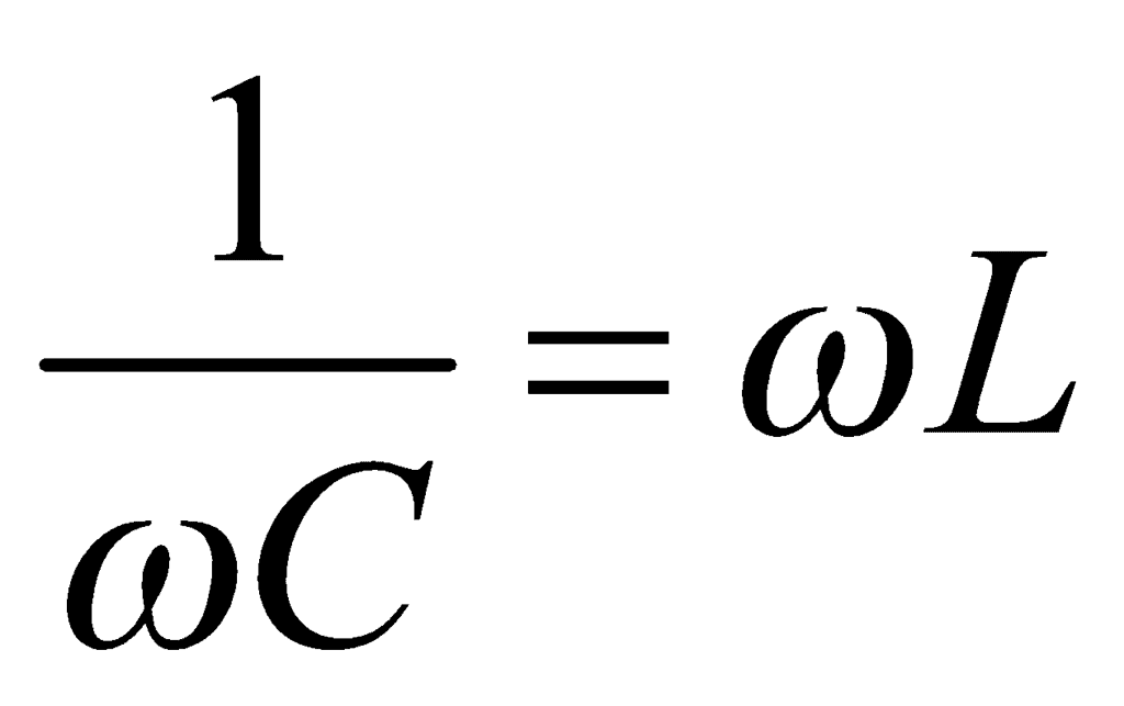 i.e.,
i.e., 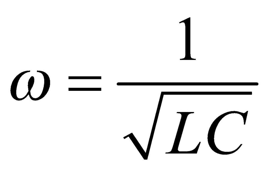
∴ 

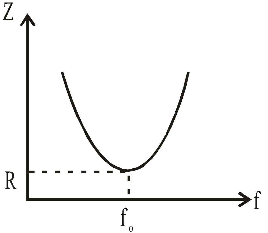
Thus the resonant frequency depends on the product of L and C and is independent of R.
At resonance, impedance is minimum, Zmin = R, and current is maximum 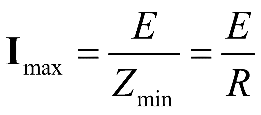

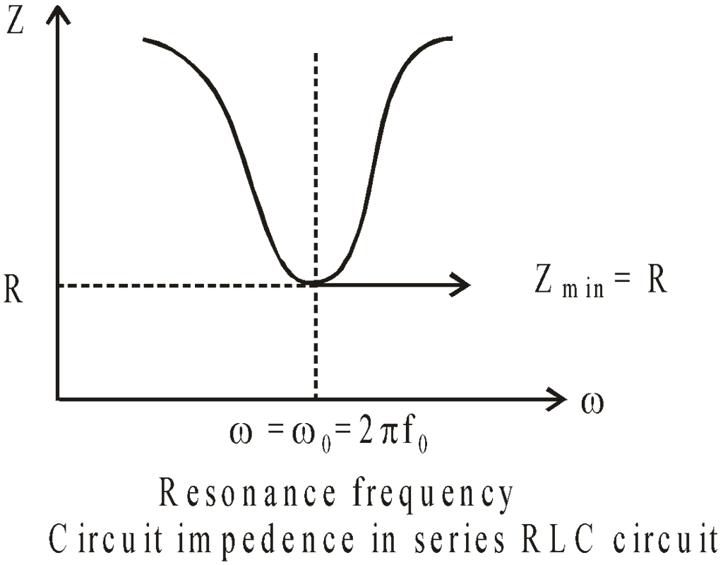
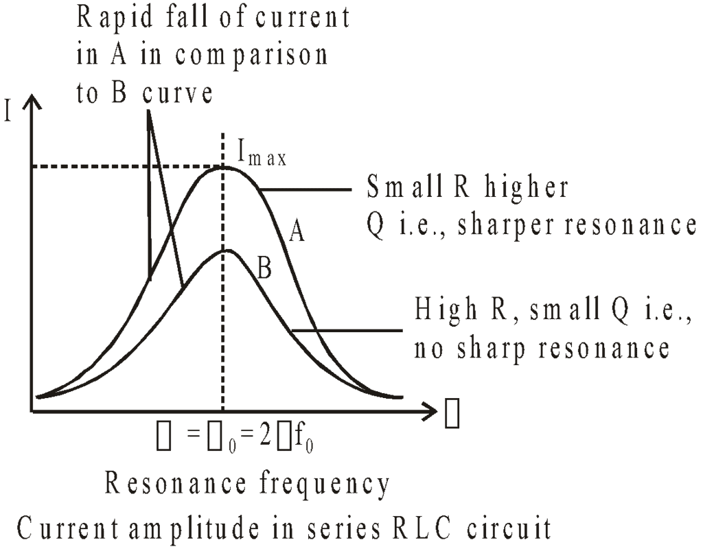
It is interesting to note that before resonance the current leads the applied emf, at resonance, it is in phase, and after resonance, it lags behind the emf. LCR series circuit is also called an acceptor circuit and a parallel LCR circuit is called a rejector circuit.
Question for LCR Circuit: Series and Parallel
Try yourself:
What is bandwidth?View Solution
Parallel LCR Circuit
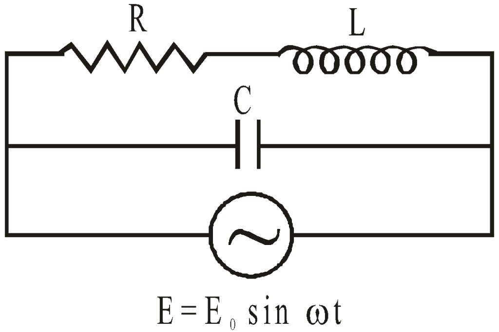 Parallel LCR Circuit
The condition of resonance is again that the current and applied emf must be in the same phase. The condition gives angular resonant frequency as:
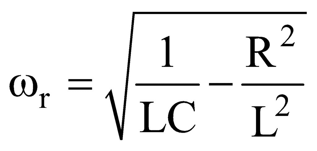
∴ Resonant frequency 

The impedance at resonance, 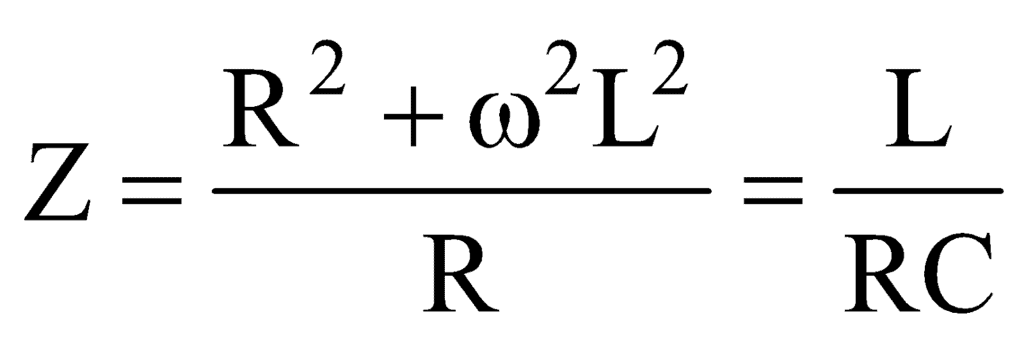

In a parallel resonant circuit, the impedance is maximum and the current is minimum.
If, then 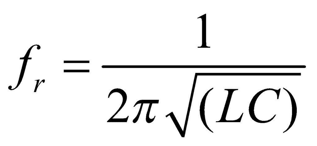 and
and 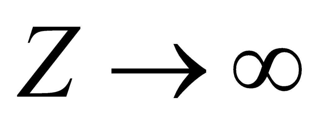 .
.
 and
and  .
.Q - Factor
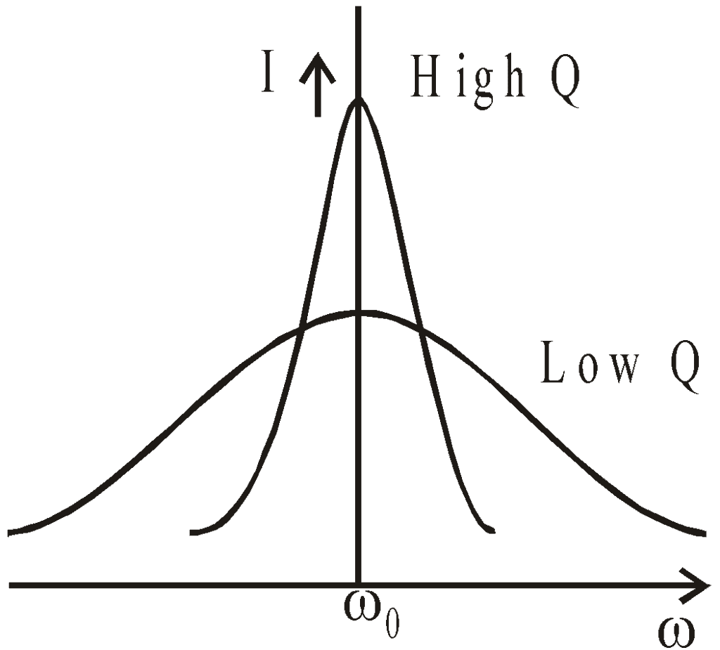
The sharpness of tuning at resonance is measured by the Q-factor or the quality factor of the circuit is given by:
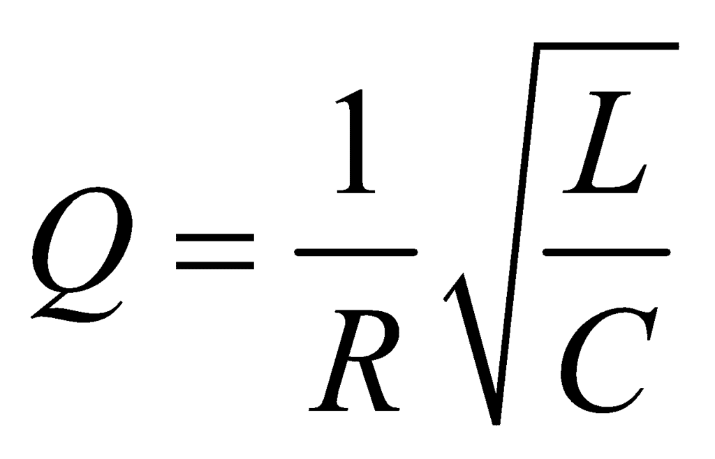
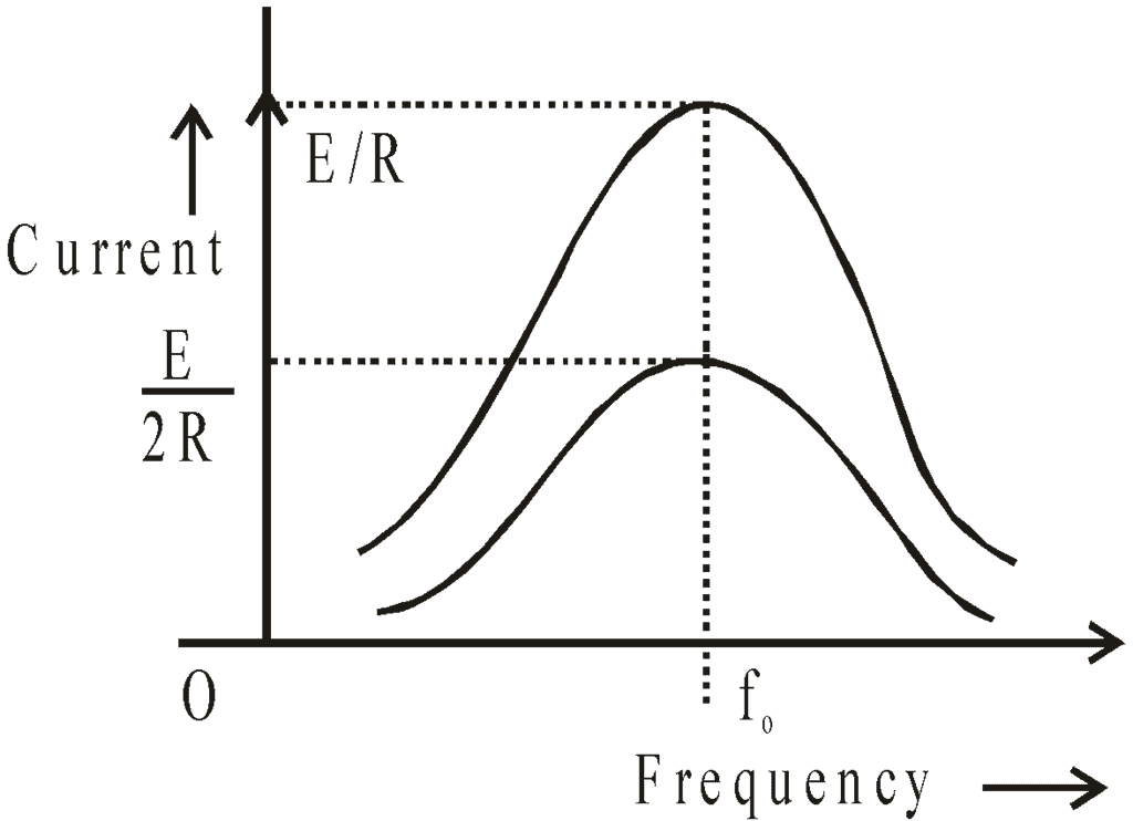
The higher the value of the Q-factor, the sharper the resonance i.e. more rapid is the fall of current from maximum value (I0) with a slight change in frequency from the resonance value.
It is clear from the figure that at a low value of θ, the resonance is poor. However the bandwidth increases.
The figure given below explains the concept of bandwidth and cut-off frequency.
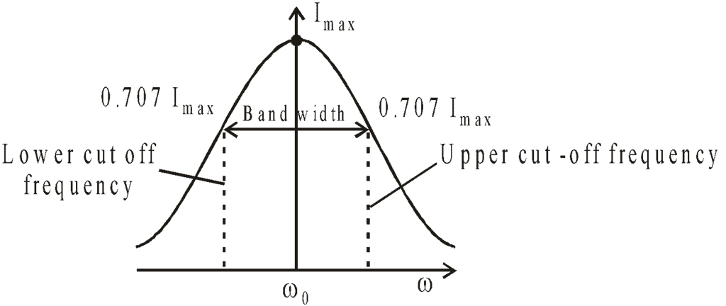
Bandwidth: It is the band of allowed frequencies and is defined as the difference between upper and lower cut-off frequencies, the frequency at which power becomes half of the maximum value and currently becomes, 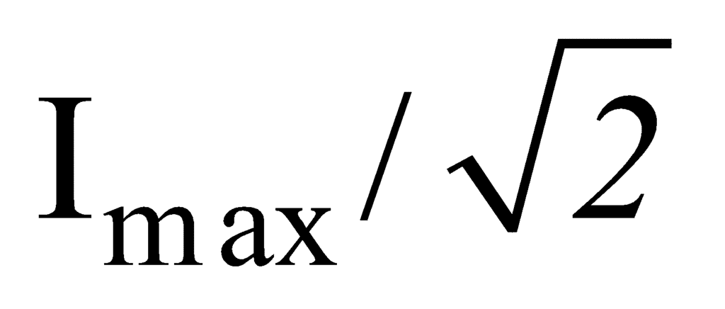 .
.
 .
.FAQs on LCR Circuit: Series and Parallel - Class 12
| 1. What is an LCR circuit? |  |
| 2. What is the difference between a series LCR circuit and a parallel LCR circuit? |  |
Ans. In a series LCR circuit, the components (inductor, capacitor, and resistor) are connected in a series, meaning that the same current flows through each component. In a parallel LCR circuit, the components are connected in parallel, meaning that the voltage across each component is the same. The behavior and characteristics of these circuits differ, and their applications vary accordingly.
| 3. What is the significance of an LCR circuit in electrical engineering? |  |
Ans. LCR circuits have significant applications in electrical engineering. They are used in various devices, such as filters, oscillators, amplifiers, and impedance matching circuits. LCR circuits also play a crucial role in understanding and analyzing the behavior of AC circuits, resonance phenomena, and power factor correction.
| 4. How does an LCR circuit work? |  |
Ans. In an LCR circuit, the inductor, capacitor, and resistor interact with each other to create a complex impedance. The inductor resists changes in current, the capacitor resists changes in voltage, and the resistor dissipates energy. The behavior of the circuit depends on the frequency of the applied voltage and the values of the components.
| 5. What are the applications of series and parallel LCR circuits? |  |
Ans. Series LCR circuits are commonly used in applications such as filters, where the circuit can be designed to pass or block specific frequencies. Parallel LCR circuits are often used in impedance matching applications, where the circuit is designed to maximize power transfer between different components. Both types of circuits are also used in the design and analysis of electrical systems and components.
Related Searches


