Concept of Resonance and Delocalization of electrons | Chemistry Optional Notes for UPSC PDF Download
Introduction
Resonance is a way of describing delocalized electrons within certain molecules or polyatomic ions where the bonding cannot be expressed by a single Lewis formula. A molecule or ion with such delocalized electrons is represented by several resonance structures. The nuclear skeleton of the Lewis Structure of these resonance structures remains the same, only the electron locations differ. Such is the case for ozone (O3), an allotrope of oxygen with a V-shaped structure and an O–O–O angle of 117.5°. Let's motivate the discussion by building the Lewis structure for ozone.
- We know that ozone has a V-shaped structure, so one O atom is central:

- Each O atom has 6 valence electrons, for a total of 18 valence electrons.
- Assigning one bonding pair of electrons to each oxygen–oxygen bond gives
 with 14 electrons left over.
 - If we place three lone pairs of electrons on each terminal oxygen, we obtain
 and have 2 electrons left over.
 - At this point, both terminal oxygen atoms have octets of electrons. We therefore place the last 2 electrons on the central atom:

- The central oxygen has only 6 electrons. We must convert one lone pair on a terminal oxygen atom to a bonding pair of electrons—but which one? Depending on which one we choose, we obtain either

Which is correct? In fact, neither is correct. Both predict one O–O single bond and one O=O double bond. As you will learn, if the bonds were of different types (one single and one double, for example), they would have different lengths. It turns out, however, that both O–O bond distances are identical, 127.2 pm, which is shorter than a typical O–O single bond (148 pm) and longer than the O=O double bond in O2 (120.7 pm).
Equivalent Lewis dot structures, such as those of ozone, are called resonance structures. The position of the atoms is the same in the various resonance structures of a compound, but the position of the electrons is different. Double-headed arrows link the different resonance structures of a compound:
The double-headed arrow indicates that the actual electronic structure is an average of those shown, not that the molecule oscillates between the two structures.
- When it is possible to write more than one equivalent resonance structure for a molecule or ion, the actual structure is the average of the resonance structures.
The electrons appear to "shift" between different resonance structures and while not strictly correct as each resonance structure is just a limitation of using the Lewis structure perspective to describe these molecules. A more accurate description of the electron structure of the molecule requires considering multiple resonance structures simultaneously.
Delocalization and Resonance Structures Rules
- Resonance structures should have the same number of electrons, do not add or subtract any electrons. (check the number of electrons by simply counting them).
- Each resonance structures follows the rules of writing Lewis Structures.
- The hybridization of the structure must stay the same.
- The skeleton of the structure can not be changed (only the electrons move).
- Resonance structures must also have the same number of lone pairs.
Solved Example
Example: Identify the resonance structures for the carbonate ion:  .
.
Ans: Because carbon is the least electronegative element, we place it in the central position: Carbon has 4 valence electrons, each oxygen has 6 valence electrons, and there are 2 more for the −2 charge. This gives 4 + (3 × 6) + 2 = 24 valence electrons.
Six electrons are used to form three bonding pairs between the oxygen atoms and the carbon: We divide the remaining 18 electrons equally among the three oxygen atoms by placing three lone pairs on each and indicating the −2 charge:
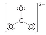 No electrons are left for the central atom.
At this point, the carbon atom has only 6 valence electrons, so we must take one lone pair from an oxygen and use it to form a carbon–oxygen double bond. In this case, however, there are three possible choices: As with ozone, none of these structures describes the bonding exactly. Each predicts one carbon–oxygen double bond and two carbon–oxygen single bonds, but experimentally all C–O bond lengths are identical. We can write resonance structures (in this case, three of them) for the carbonate ion:
 The actual structure is an average of these three resonance structures.
Like ozone, the electronic structure of the carbonate ion cannot be described by a single Lewis electron structure. Unlike O3, though, the actual structure of CO32− is an average of three resonance structures.
Using Formal Charges to Identify viable Resonance Structures
While each resonance structure contributes to the total electronic structure of the molecule, they may not contribute equally. Assigning Formal charges to atoms in the molecules is one mechanism to identify the viability of a resonance structure and determine its relative magnitude among other structures. The formal charge on an atom in a covalent species is the net charge the atom would bear if the electrons in all the bonds to the atom were equally shared. Alternatively the formal charge on an atom in a covalent species is the net charge the atom would bear if all bonds to the atom were nonpolar covalent bonds. To determine the formal charge on a given atom in a covalent species, use the following formula:
Formal Charge = (number of valence electrons in free orbital) − (number of lone-pair electrons) − 1/2 ( number bond pair electrons) (1)
Rules for estimating stability of resonance structures
- The greater the number of covalent bonds, the greater the stability since more atoms will have complete octets
- The structure with the least number of formal charges is more stable
- The structure with the least separation of formal charge is more stable
- A structure with a negative charge on the more electronegative atom will be more stable
- Positive charges on the least electronegative atom (most electropositive) is more stable
- Resonance forms that are equivalent have no difference in stability and contribute equally (eg. benzene)
Solved Examples
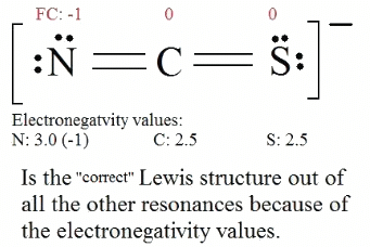
Example 1: Consider the thiocyanate (CNS−) ion.
Ans: 1. Find the Lewis Structure of the molecule. (Remember the Lewis Structure rules.) 2. Resonance: All elements want an octet, and we can do that in multiple ways by moving the terminal atom's electrons around (bonds too).
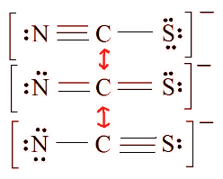 3. Assign Formal Charges via Equation 1.
Formal Charge = (number of valence electrons in free orbital) - (number of lone-pair electrons) - ( 1/2 number bond pair electrons) Remember to determine the number of valence electron each atom has before assigning Formal Charges
C = 4 valence e-, N = 5 valence e-, S = 6 valence e-, also add an extra electron for the (-1) charge. The total of valence electrons is 16.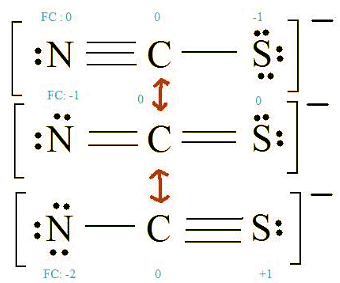 4. Find the most ideal resonance structure. (Note: It is the one with the least formal charges that adds up to zero or to the molecule's overall charge.)
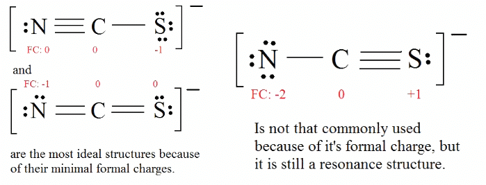
5. Now we have to look at electronegativity for the "Correct" Lewis structure. The most electronegative atom usually has the negative formal charge, while the least electronegative atom usually has the positive formal charges.
It is useful to combine the resonance structures into a single structure called the Resonance Hybrid that describes the bonding of the molecule. The general approach is described below:
- Draw the Lewis Structure & Resonance for the molecule (using solid lines for bonds).
- Where there can be a double or triple bond, draw a dotted line (-----) for the bond.
- Draw only the lone pairs found in all resonance structures, do not include the lone pairs that are not on all of the resonance structures.
Example 2: Benzene is a common organic solvent that was previously used in gasoline; it is no longer used for this purpose, however, because it is now known to be a carcinogen. The benzene molecule (C6H6) consists of a regular hexagon of carbon atoms, each of which is also bonded to a hydrogen atom. Use resonance structures to describe the bonding in benzene.
Given: molecular formula and molecular geometry
Asked for: resonance structures
Strategy:
(a) Draw a structure for benzene illustrating the bonded atoms. Then calculate the number of valence electrons used in this drawing.
(b) Subtract this number from the total number of valence electrons in benzene and then locate the remaining electrons such that each atom in the structure reaches an octet.
(c) Draw the resonance structures for benzene.
Ans: (a) Each hydrogen atom contributes 1 valence electron, and each carbon atom contributes 4 valence electrons, for a total of (6 × 1) + (6 × 4) = 30 valence electrons. If we place a single bonding electron pair between each pair of carbon atoms and between each carbon and a hydrogen atom, we obtain the following:
Each carbon atom in this structure has only 6 electrons and has a formal charge of +1, but we have used only 24 of the 30 valence electrons.
(b) If the 6 remaining electrons are uniformly distributed pairwise on alternate carbon atoms, we obtain the following:
 Three carbon atoms now have an octet configuration and a formal charge of −1, while three carbon atoms have only 6 electrons and a formal charge of +1. We can convert each lone pair to a bonding electron pair, which gives each atom an octet of electrons and a formal charge of 0, by making three C=C double bonds.
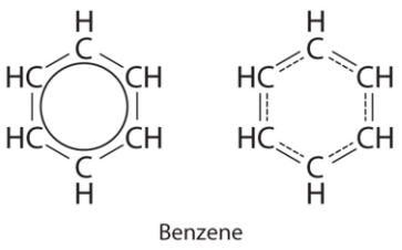
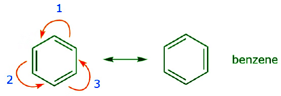
(c) There are, however, two ways to do this: Each structure has alternating double and single bonds, but experimentation shows that each carbon–carbon bond in benzene is identical, with bond lengths (139.9 pm) intermediate between those typically found for a C–C single bond (154 pm) and a C=C double bond (134 pm). We can describe the bonding in benzene using the two resonance structures, but the actual electronic structure is an average of the two. The existence of multiple resonance structures for aromatic hydrocarbons like benzene is often indicated by drawing either a circle or dashed lines inside the hexagon:
Example 3: Draw the possible resonance structures for the Nitrate ion NO−3
Ans:
1. Count up the valence electrons: (1*5) + (3*6) + 1(ion) = 24 electrons
2. Draw the bond connectivities: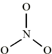
3. Add octet electrons to the atoms bonded to the center atom:
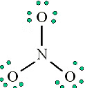
4. Place any leftover electrons (24-24 = 0) on the center atom: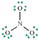
5. Does the central atom have an octet?
- NO, it has 6 electrons
- Add a multiple bond (first try a double bond) to see if the central atom can achieve an octet:
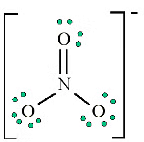
6. Does the central atom have an octet?
- YES
- Are there possible resonance structures? YES

Note: We would expect that the bond lengths in the NO−3 ion to be somewhat shorter than a single bond.
Mobility of π Electrons and Unshared Electron Pairs
Now that we understand the difference between sigma and π electrons, we remember that the π bond is made up of loosely held electrons that form a diffuse cloud which can be easily distorted. This can be illustrated by comparing two types of double bonds, one polar and one nonpolar. The C=C double bond on the left below is nonpolar. Therefore the π electrons occupy a relatively symmetric molecular orbital that’s evenly distributed (shared) over the two carbon atoms. The C=O double bond, on the other hand, is polar due to the higher electronegativity of oxygen. The π cloud is distorted in a way that results in higher electron density around oxygen compared to carbon. Both atoms still share electrons, but the electrons spend more time around oxygen. The drawing on the right tries to illustrate that concept.
Using simple Lewis formulas, or even line-angle formulas, we can also draw some representations of the two cases above, as follows.

The dynamic nature of π electrons can be further illustrated with the use of arrows, as indicated below for the polar C=O bond:
Curved Arrows Formalism
The CURVED ARROW FORMALISM is a convention used to represent the movement of electrons in molecules and reactions according to certain rules. We’ll study those rules in some detail. For now, we keep a few things in mind:
- Curved arrows always represent the movement of electrons, not atoms.
- Electrons always move towards more electronegative atoms or towards positive charges.
We notice that the two structures shown above as a result of “pushing electrons” towards the oxygen are RESONANCE STRUCTURES. That is to say, they are both valid Lewis representations of the same species. The actual species is therefore a hybrid of the two structures. We conclude that:
- Curved arrows can be used to arrive from one resonance structure to another by following certain rules.
Just like π electrons have a certain degree of mobility due to the diffuse nature of π molecular orbitals, unshared electron pairs can also be moved with relative ease because they are not engaged in bonding. No bonds have to be broken to move those electrons. As a result, we keep in mind the following principles:
- Curved arrows usually originate with π electrons or unshared electron pairs, and point towards more electronegative atoms, or partial or full positive charges.
Going back to the two resonance structures shown before, we can use the curved arrow formalism either to arrive from structure I to structure II, or vice versa.

In case A, the arrow originates with π electrons, which move towards the more electronegative oxygen. In case B, the arrow originates with one of the unshared electron pairs, which moves towards the positive charge on carbon. We further notice that π electrons from one structure can become unshared electrons in another, and vice versa. We’ll look at additional guidelines for how to use mobile electrons later.
- Finally, in addition to the above, we notice that the oxygen atom, for example, is sp2 hybridized (trigonal planar) in structure I, but sp3 hybridized (tetrahedral) in structure II. So, which one is it? Again, what we are talking about is the real species. The real species is a hybrid that contains contributions from both resonance structures. In this particular case, the best we can do for now is issue a qualitative statement: since structure, I is the major contributor to the hybrid, we can say that the oxygen atom in the actual species is mostly trigonal planar because it has greater sp2 character, but it still has some tetrahedral character due to the minor contribution from structure II. We’ll explore and expand on this concept in a variety of contexts throughout the course.
- What about sigma electrons, that is to say those forming part of single bonds? These bonds represent the “glue” that holds the atoms together and are a lot more difficult to disrupt. As a result, they are not as mobile as π electrons or unshared electrons, and are therefore rarely moved. There are however some exceptions, notably with highly polar bonds, such as in the case of HCl illustrated below. We will not encounter such situations very frequently.

This representation better conveys the idea that the H–Cl bond is highly polar.
Using Curved Arrows
We now go back to an old friend of ours, CH3CNO, which we introduced when we first talked about resonance structures. We use this compound to further illustrate how mobile electrons are “pushed” to arrive from one resonance structure to another. The movement of electrons that takes place to arrive at structure II from structure I starts with the triple bond between carbon and nitrogen. We’ll move one of the two π bonds that form part of the triple bond towards the positive charge on nitrogen, as shown:
 When we do this, we pay close attention to the new status of the affected atoms and make any necessary adjustments to the charges, bonds, and unshared electrons to preserve the validity of the resulting formulas. In this case, for example, the carbon that forms part of the triple bond in structure I has to acquire a positive charge in structure II because it’s lost one electron. The nitrogen, on the other hand, is now neutral because it gained one electron and it’s forming three bonds instead of four.
We can also arrive from structure I to structure III by pushing electrons in the following manner. The arrows have been numbered in this example to indicate which movement starts first, but that’s not part of the conventions used in the curved arrow formalism.
As we move a pair of unshared electrons from oxygen towards the nitrogen atom as shown in step 1, we are forced to displace electrons from nitrogen towards carbon as shown in step 2. Otherwise we would end up with a nitrogen with 5 bonds, which is impossible, even if only momentarily. Again, notice that in step 1 the arrow originates with an unshared electron pair from oxygen and moves towards the positive charge on nitrogen. A new π bond forms between nitrogen and oxygen. At the same time, the π electrons being displaced towards carbon in step 2 become a pair of unshared electrons in structure III. Finally, the hybridization state of some atoms also changes. For example the carbon atom in structure I is sp hybridized, but in structure III it is sp3 hybridized. You may want to play around some more and see if you can arrive from structure II to structure III, etc. However, be warned that sometimes it is trickier than it may seem at first sight.
Additional rules for moving electrons to write Resonance Structures:
- Electron pairs can only move to adjacent positions. Adjacent positions means neighboring atoms and/or bonds.
- The Lewis structures that result from moving electrons must be valid and must contain the same net charge as all the other resonance structures.
The following example illustrates how a lone pair of electrons from carbon can be moved to make a new π bond to an adjacent carbon, and how the π electrons between carbon and oxygen can be moved to become a pair of unshared electrons on oxygen. None of the previous rules has been violated in any of these examples. Now let’s look at some examples of HOW NOT TO MOVE ELECTRONS. Using the same example, but moving electrons in a different way, illustrates how such movement would result in invalid Lewis formulas, and therefore is unacceptable. Not only are we moving electrons in the wrong direction (away from a more electronegative atom), but the resulting structure violates several conventions. First, the central carbon has five bonds and therefore violates the octet rule. Second, the overall charge of the second structure is different from the first. To avoid having a carbon with five bonds we would have to destroy one of the C–C single bonds, destroying the molecular skeleton in the process.
 In the example below electrons are being moved towards an area of high electron density (a negative charge), rather than towards a positive charge. In addition, the octet rule is violated for carbon in the resulting structure, where it shares more than eight electrons.
Additional examples further illustrate the rules we’ve been talking about.
(a) Unshared electron pairs (lone pairs) located on a given atom can only move to an adjacent position to make a new π bond to the next atom.

(b) Unless there is a positive charge on the next atom (carbon above), other electrons will have to be displaced to preserve the octet rule. In resonance structures these are almost always π electrons, and almost never sigma electrons.
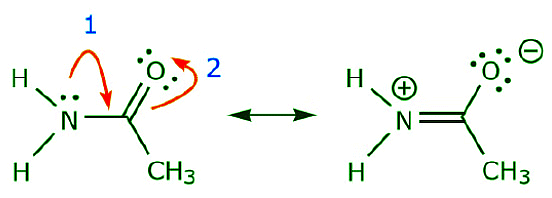
As the electrons from the nitrogen lone pair move towards the neighboring carbon to make a new π bond, the π electrons making up the C=O bond must be displaced towards the oxygen to avoid ending up with five bonds to the central carbon.
(c) As can be seen above, π electrons can move towards one of the two atoms they share to form a new lone pair. In the example above, the π electrons from the C=O bond moved towards the oxygen to form a new lone pair. Another example is:

(d) π electrons can also move to an adjacent position to make new π bond. Once again, the octet rule must be observed:

One of the most common examples of this feature is observed when writing resonance forms for benzene and similar rings.
Delocalization, Conjugated Systems, and Resonance Energy
- The presence of alternating π and σ bonds in a molecule such as benzene is known as a conjugated system, or conjugated π bonds. Conjugated systems can extend across the entire molecule, as in benzene, or they can comprise only part of a molecule. A conjugated system always starts and ends with a π bond (i.e. an sp2 or an sp -hybridized atom), or sometimes with a charge. The atoms that form part of a conjugated system in the examples below are shown in blue and the ones that do not are shown in red. Most of the times it is sp3 hybridized atoms that break a conjugated system.

- Practically every time there are π bonds in a molecule, especially if they form part of a conjugated system, there is a possibility for having resonance structures, that is, several valid Lewis formulas for the same compound. What resonance forms show is that there is electron delocalization, and sometimes charge delocalization. All the examples we have seen so far show that electrons move around and are not static, that is, they are delocalized. Charge delocalization is a stabilizing force because it spreads energy over a larger area rather than keeping it confined to a small area. Since electrons are charges, the presence of delocalized electrons brings extra stability to a system compared to a similar system where electrons are localized. The stabilizing effect of charge and electron delocalization is known as resonance energy.
Since conjugation brings up electron delocalization, it follows that the more extensive the conjugated system, the more stable the molecule (i.e. the lower its potential energy). If there are positive or negative charges, they also spread out as a result of resonance.
- The more resonance forms one can write for a given system, the more stable it is. That is, the greater its resonance energy.
Examine the following examples and write as many resonance structures as you can for each to further explore these points:
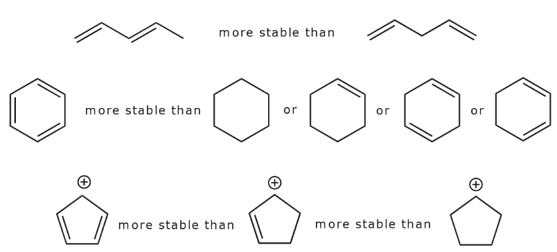
Let’s look for a moment at the three structures in the last row above. In the first structure, delocalization of the positive charge and the π bonds occurs over the entire ring. This becomes apparent when we look at all the possible resonance structures as shown below.
 In the second structure, delocalization is only possible over three carbon atoms. This is demonstrated by writing all the possible resonance forms below, which now number only two.
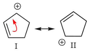
Finally, the third structure has no delocalization of charge or electrons because no resonance forms are possible. Therefore, it is the least stable of the three. This brings us to the last topic. How do we recognize when delocalization is possible? Let’s look at some delocalization setups, that is to say, structural features that result in delocalization of electrons.
Delocalization Setups
There are specific structural features that bring up electron or charge delocalization. The presence of a conjugated system is one of them. Other common arrangements are:
(a) The presence of a positive charge next to a π bond. The positive charge can be on one of the atoms that make up the π bond, or on an adjacent atom.
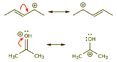 (b) The presence of a positive charge next to an atom bearing lone pairs of electrons.
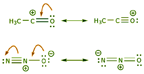 (c) The presence of a π bond next to an atom bearing lone pairs of electrons.
Orbital Pictures of Delocalization
The orbital view of delocalization can get somewhat complicated. For now we’re going to keep it at a basic level. We start by noting that sp2 carbons actually come in several varieties. Two of the most important and common are neutral sp2 carbons and positively charged sp2 carbons. Substances containing neutral sp2 carbons are regular alkenes. Species containing positively charged sp2 carbons are called carbocations. The central carbon in a carbocation has trigonal planar geometry, and the unhybridized p orbital is empty. The following representations convey these concepts.
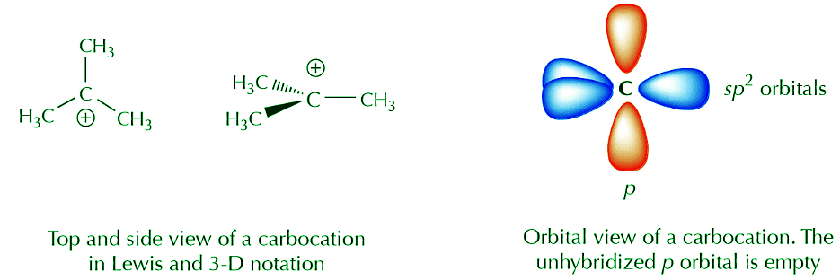
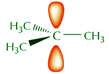
A combination of orbital and Lewis or 3-D formulas is a popular means of representing certain features that we may want to highlight. For example, if we’re not interested in the sp2 orbitals and we just want to focus on what the p orbitals are doing we can use the following notation.
 Let’s now focus on two simple systems where we know delocalization of π electrons exists. One is a system containing two pi bonds in conjugation, and the other has a pi bond next to a positively charged carbon. We can represent these systems as follows.

If we focus on the orbital pictures, we can immediately see the potential for electron delocalization. The two π molecular orbitals shown in red on the left below are close enough to overlap. Overlapping is a good thing because it delocalizes the electrons and spreads them over a larger area, bringing added stability to the system.

It is however time-consuming to draw orbitals all the time. The following representations are used to represent the delocalized system.
A similar process applied to the carbocation leads to a similar picture.
The resonance representation conveys the idea of delocalization of charge and electrons rather well.
Finally, the following representations are sometimes used, but again, the simpler they are, the less accurately they represent the delocalization picture. There will be plenty of opportunity to observe more complex situations as the course progresses.
FAQs on Concept of Resonance and Delocalization of electrons - Chemistry Optional Notes for UPSC
| 1. What is the concept of resonance in organic chemistry? |  |
| 2. How can formal charges be used to identify viable resonance structures? |  |
| 3. What is the significance of delocalization and conjugated systems in organic chemistry? |  |
| 4. How can curved arrows be used in the context of resonance structures? |  |
| 5. What is resonance energy and how is it related to delocalization in organic molecules? |  |


