Head Losses in Pipes and Pipe Fittings | Fluid Mechanics for Civil Engineering - Civil Engineering (CE) PDF Download
Pipe Friction Loss Calculations
Flow of fluid through a pipe is resisted by viscous shear stresses within the fluid and the turbulence that occurs along the internal pipe wall, which is dependent on the roughness of the pipe material.
This resistance is termed pipe friction and is usually measured in feet or metres head of the fluid, which is why it is also refered to as the head loss due to pipe friction.
Secondary Losses of Head in Pipes
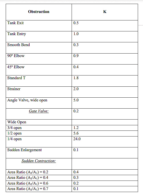
Any alteration in a pipe, whether in direction, diameter, or with the inclusion of a valve or other fittings, leads to energy loss resulting from disruption in the flow.

The velocity 'v' represents the entry velocity into the fitting. In cases where the velocity differs upstream and downstream of the section, the higher velocity is typically considered.

Energy Grade Line (EGL):
The energy and hydraulic grade lines are concepts used in fluid mechanics, particularly in the analysis of flow within pipes or open channels. These lines help visualize the distribution of energy and hydraulic head along the flow path.
The Energy Grade Line represents the total energy per unit weight of fluid (usually in meters or feet) along the flow path. It includes the sum of the elevation head, velocity head, and pressure head. Mathematically, it can be expressed as:
Where:
z = Elevation head (meters or feet)
v = Velocity of the fluid (m/s or ft/s)
g = Acceleration due to gravity (m/s2 orEGL = z + (v2)/(2g) + (P)/(γ ft/s2)
P = Pressure head (N/m² or lb/ft2)
γ = Specific weight of the fluid (N/m3 or lb/ft3)
Hydraulic Grade Line (HGL):
The Hydraulic Grade Line represents the sum of the elevation head and pressure head along the flow path, neglecting the velocity head. Mathematically, it can be expressed as:
HGL = z + (P)/(γ)
Where the terms are the same as those defined for the EGL.
The EGL and HGL help engineers and designers understand the distribution of energy and pressure in a fluid system. In a steady, uniform flow, the EGL and HGL should coincide. However, in real-world scenarios, especially in systems with significant changes in velocity and pressure, there might be a difference between the two lines, indicating the presence of energy losses such as friction losses, bends, or expansions.
In a typical pipe system, the EGL decreases along the flow direction due to energy losses, while the HGL decreases due to head losses but increases in the direction of flow due to the decrease in pressure head. The difference between EGL and HGL represents the velocity head, indicating the kinetic energy of the flowing fluid.
|
54 videos|141 docs|115 tests
|


