Class 10 Exam > Class 10 Notes > Computer for GCSE/IGCSE > Truth Tables
Truth Tables | Computer for GCSE/IGCSE - Class 10 PDF Download
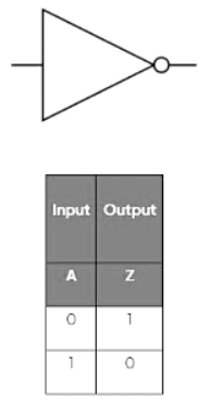
NOT gate
- A NOT gate has one input and produces an opposite output by inverting it.
- A is the input
- Z is the output
AND gate
- An AND gate requires two inputs to produce an output.
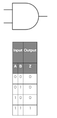
- The AND gate's truth table demonstrates that only when both inputs are 1, a positive output is produced.
OR Gate
- An OR gate requires two inputs to operate.
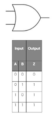
- The truth table illustrates that an OR gate generates a 1 output if any of its inputs are 1.
NOR Gate
- A NOR gate also has two inputs.
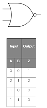
- The truth table demonstrates that a NOR gate functions in the opposite manner to an OR gate; the only input combination that yields a 1 output is when both inputs are 0.
NAND Gate
A NAND gate has two inputs
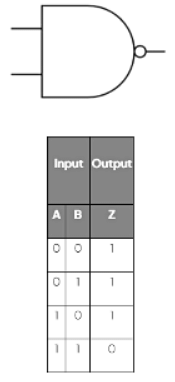
- The truth table indicates that a NAND gate operates inversely to an AND gate; the only input combination that does not produce a 1 output is when both inputs are positive (1 +1).
The XOR Gate
- The XOR gate has two inputs.
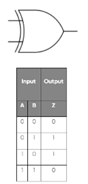
- The truth table illustrates the functioning of an XOR gate: it only produces a 1 output when the two inputs are not identical.
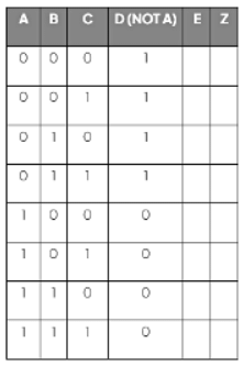
- When constructing a truth table for multiple inputs, start by listing the potential input combinations in the leftmost columns.
A truth table for a three input (A, B and C) logic gate
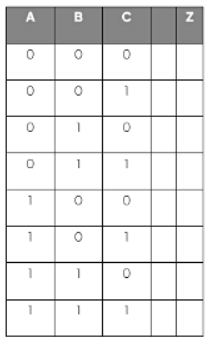
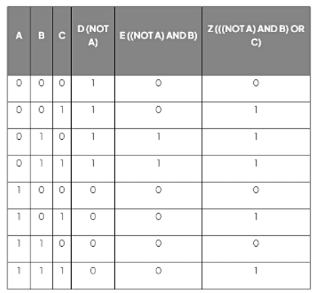
- The rightmost column displays the ultimate output of the logic circuit (Z).
- Intermediate columns situated between the inputs and the final output aid in determining the ultimate output by holding intermediary results.
- These intermediary results represent the outputs of gates present within the logic circuit.
- Within the given logic circuit diagram, D and E serve as intermediary outputs.
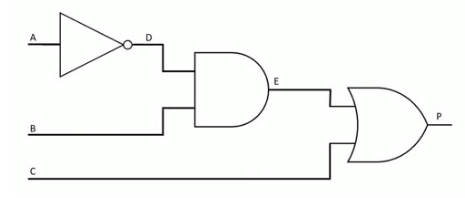
- The fourth column labelled D represents the output of NOT A
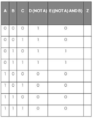
- The subsequent intermediary output, E, is determined by the logic expression ((NOT A) AND B). This notation is known as a logic expression.
- The E intermediary output is calculated by executing the AND logical operation on columns B and D.
- The final output (Z) can be worked out by performing the OR logical operation on columns E and C
The document Truth Tables | Computer for GCSE/IGCSE - Class 10 is a part of the Class 10 Course Computer for GCSE/IGCSE.
All you need of Class 10 at this link: Class 10
|
109 docs|32 tests
|
Related Searches


