Textbook Solution: Electricity and Circuits | IGCSE Cambridge Science for Year 7 - Class 7 PDF Download
| Table of contents |

|
| Charge Flow in Circuits |

|
| Circuit Diagrams |

|
| Currents in the Circuits |

|
| End of the Chapter Review |

|
| End of the Stage Review |

|
Charge Flow in Circuits
Q1. Will the lamp come on as soon as the switch is closed?
Ans: Yes, the lamp will come on as soon as the switch is closed, provided the circuit is complete and the bulb is functional.
Q2. Would moving the switch to the opposite side of the circuit make a difference?
Ans: No, moving the switch to the opposite side of the circuit will not make a difference in how the circuit functions. The switch will still control the flow of current regardless of its position in the circuit.
Q3. Decide whether these statements are true or false. If false, write a correct version.
a) The teacher represents the lamp.
Ans : False
Correct version: The teacher does not represent the lamp; the teacher represents a power source such as a battery.
b) When the teacher pulls the rope he supplies electric charge.
Ans : False
Correct version: When the teacher pulls the rope, he simulates the movement of electric charge in the circuit.
c) The flow of rope represents the current in the circuit.
Ans: True
Q4. Which group of materials are conductors?
Ans: Conductors are materials that allow electricity to flow through them easily. Examples include metals like copper, aluminum, and silver.
Q5. Which group of materials are insulators?
Ans: Insulators are materials that do not conduct electricity well. Examples include rubber, plastic, glass, and wood.
Q6. Why are copper wires usually covered with plastic?
Ans: Copper wires are usually covered with plastic to insulate them, preventing accidental electric shocks and protecting the wires from environmental damage.
Q7. Copper wire doesn’t get hot when current flows. Nichrome is a metal which has fewer free electrons, so doesn’t conduct as well as copper. Explain why nichrome wire gets hot when current flows (think about the rope loop model).
Ans: Nichrome wire gets hot when current flows because it has higher electrical resistance compared to copper. In the rope loop model, this can be represented by imagining the rope moving through a narrow space where friction generates heat.
Circuit Diagrams
Q1. Look at the circuits in figure 9.10. Identify which is a series circuit and which is a parallel circuit.
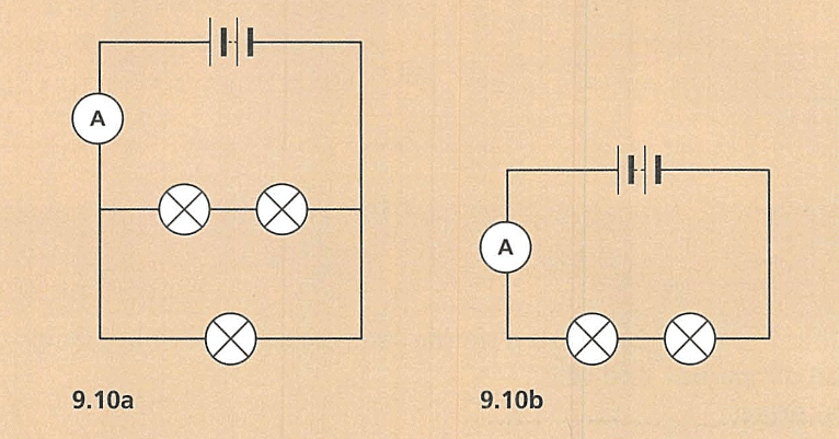
Ans: In figure 9.10a, the circuit is a series circuit. In figure 9.10b, the circuit is a parallel circuit.
Q2. Draw a series circuit with three lamps, an ammeter, a switch, and two cells.
Ans: A series circuit with these components would have all elements connected in a single loop. The cells would be connected to feed power to the circuit, followed by the switch, the ammeter, and then the three lamps in sequence before returning to the negative terminal of the cells.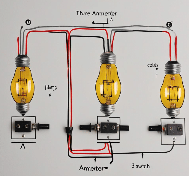
Q3. In the rope loop model, what do these parts of the model represent:
a) the people pulling the rope?
Ans: They represent a power source like a battery or generator.
b) the people gripping the rope?
Ans: They represent resistors in the circuit that impede the flow of electricity.
c) the flow of the rope? -
Ans: It represents the electric current flowing through the circuit.
Q4. Using your answers to Question 3, predict and explain what would happen to the lamps if:
a) more cells are added to a circuit.
Ans: The lamps would generally become brighter, as adding more cells increases the voltage, thus increasing the current through the lamps if resistance remains constant.
b) more lamps are added to the circuit.
Ans: The lamps would generally become dimmer, as adding more lamps increases the total resistance, which reduces the current flowing through each lamp if the voltage remains constant.
Q5. A circuit has one cell and two lamps. A student adds another cell and two more lamps to the same circuit. Will the lamps be brighter, dimmer, or the same as the original circuit?
Ans: The lamps would be the same as the original circuit. Adding both more cells and more lamps keeps the overall voltage to resistance ratio similar, assuming the cells and lamps are all identical.
Currents in the Circuits
Q1. A student says that current gets less as it goes around a circuit. Explain why this is wrong.
Ans: This statement is incorrect because the current in a circuit remains constant as it travels around the circuit. This constant flow occurs because electric current, which is the flow of charged particles, must be conserved in a closed loop, much like the amount of water flowing through a hose is the same at any point in the hose. If the current were to decrease, there would need to be a loss of energy or charge at some point, which does not occur in a standard closed circuit.
Q2. Describe how you could use the rope loop model to explain your answer to Question 1.
Ans: The rope loop model can be used to explain the constancy of electric current in a circuit by likening the circuit to a loop of rope being continuously pulled. In this model, the rope represents the current, and the person pulling the rope can be considered as the battery or energy source. Just as the speed and amount of rope that passes through any point in the loop remains constant as long as the pulling continues evenly, the current remains the same throughout the circuit as long as the power supply remains constant
End of the Chapter Review
Q1. Draw the symbols for these components:
Ans:
(a) Switch - 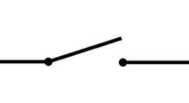 (b) Cell -
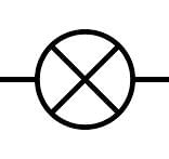
 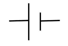 (c) Lamp -
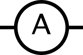
  (d) Ammeter -
Q2. Define the following:
(a) a conductor
(b) an insulator
Ans:
(a) A conductor is something that conducts electricity.
(b) An insulator does not conduct electricity.
Q3. What measuring instrument is used to measure current?
Ans: Ammeter
Q4. The rope loop model can be used to explain current. Complete these sentences to identify what each part of the model represents. Use the answers from words in the box.
Ans: The person pulling the rope represents the cell. This supplies energy. The electric charge is represented by the rope. The amount of rope flowing each second represents the current. The lamp is represented by the person gripping the rope.
Q5. A student makes a circuit with one cell and one lamp. Describe and explain what will happen if:
(a) She adds an extra cell
(b) She removes the extra cell and adds an extra lamp
Ans:
(a) The lamp will be brighter because there is more voltage supplying power to it.
(b) The lamps will be dimmer because the voltage from the cell is now divided between two lamps.
Q6. A student measures the current in the circuit shown in figure 9.17. The current at position 1 is 0.1A. What will the current be at position 3?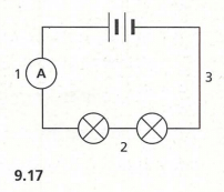
Ans: The current will be the same, 0.1A, at position 3 because the current in a series circuit remains constant.
Q7. A student wants to measure the current flowing through a lamp. They use the circuit shown in figure 9.18. Draw a circuit diagram, including an ammeter, that would measure the desired current.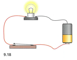
Ans: The ammeter should be connected in series with the lamp and the cell, ensuring that it is in the path of the current flowing to the lamp.
Q8. Why is it important that an ammeter is very easy for current to flow through?
Ans: It is important because an ammeter needs to measure the current without significantly altering the circuit's characteristics, such as the voltage or the current itself.
Q9. Some students did an investigation to find how the loudness of a buzzer was affected by the number of cells used to power it. The loudness of the sound was measured using a sound meter which measures sound in decibels (dB).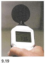

(a) Draw the circuit the students would make to test the volume for 3 cells.
(b) Why did the students repeat the experiment 3 times for each
number of cells?
(c) There is an anomaly in the results. Which result is it?
(d) Name the independent and dependent variables for this investigation.
(e) Name one variable the students would need to control.
(f) Write a conclusion for the results in the table.
Ans:
(a) To draw the circuit, the basic components you would need are:
- 3 cells (batteries) in series
- A buzzer
- Connecting wires
The circuit diagram should look something like this:
(b) Repeating the experiment multiple times ensures the reliability and accuracy of the results. It helps to identify any anomalies and reduce the impact of random errors. By taking the average of the results, students can obtain a more accurate measurement of the loudness for each number of cells.
(c) Identifying the Anomaly
Without the actual results table, I can give you a general approach to identifying anomalies. An anomaly is a result that deviates significantly from the other data points. For example, if the loudness generally increases with the number of cells, but one data point is significantly lower or higher than expected, that point would be the anomaly.
If you have a table like this (example data):
| Number of Cells | Loudness (dB) Trial 1 | Loudness (dB) Trial 2 | Loudness (dB) Trial 3 | Average Loudness (dB) |
|---|---|---|---|---|
| 1 | 50 | 51 | 52 | 51 |
| 2 | 60 | 62 | 61 | 61 |
| 3 | 70 | 85 | 72 | 75.67 |
| 4 | 80 | 81 | 82 | 81 |
In this table, the result for Trial 2 with 3 cells (85 dB) stands out as an anomaly compared to the other trials (70 dB and 72 dB).|
(d) Independent Variable: The independent variable is the number of cells used to power the buzzer. This is the variable that the students change to see how it affects the loudness.
Dependent Variable: The dependent variable is the loudness of the buzzer, measured in decibels (dB). This is the variable that the students measure in response to changes in the independent variable.
(e) One variable the students would need to control is the distance between the sound meter and the buzzer. To ensure consistent and accurate measurements of loudness, the sound meter should be placed at the same distance from the buzzer for each trial.
(f) Based on the results in the table, it can be concluded that the loudness of the buzzer increases as the number of cells powering the buzzer increases. This suggests that adding more cells, which increases the voltage supplied to the buzzer, results in a louder sound output. However, there was an anomalous result in Trial 2 with 3 cells, indicating a potential error in measurement or an inconsistency in the experimental setup for that specific trial. Overall, the trend shows a clear relationship between the number of cells and the loudness of the buzzer.
End of the Stage Review
Q1. Which of the following could never be a useful energy output of a car?
a) Fuel
b) Kinetic energy (movement)
c) Thermal energy (warmth)
d) Energy due to position (height)
Ans: d) Energy due to position (height)
Q2. A rubber ball only bounces back to half the height from which it was first dropped.
(a) What evidence does this give that energy has been dissipated?
Ans: The evidence that energy has been dissipated is that the ball does not return to its original height, indicating that some of the energy has been converted into other forms, like heat.
(b) Suggest what has happened to the dissipated energy.
Ans: The dissipated energy is likely converted into heat and sound, which are not useful for the ball's motion.
Q3. An astronaut has a mass of 80 kg. He travels from Earth to the Moon.
(a) What is the astronaut’s weight on Earth? (g = 10 N/kg on Earth)
Ans: The astronaut's weight on Earth is 800 N (80 kg * 10 N/kg).
(b) What is the astronaut’s weight on the Moon? (g = 1.5 N/kg on the Moon)
Ans: The astronaut's weight on the Moon is 120 N (80 kg * 1.5 N/kg).
(c) What is the astronaut’s mass on the Moon?
Ans: The astronaut's mass on the Moon remains the same as on Earth, 80 kg.
Q4. Draw a force diagram to show the direction and size of the forces acting on the spacecraft when it is half way between the Earth and the Moon. Show the spacecraft, the Earth and the Moon in your diagram. Label each arrow with a description of the force.
Ans:
Q5. Ali is in a thunderstorm.
(a) Explain why Ali sees the flash of lightning before he hears the thunder.
Ans: Ali sees the flash of lightning before hearing the thunder because light travels faster than sound.
(b) Ali measures the time from seeing the lightning to hearing the thunder. Write down which flash of lightning is closest to him.
Ans: The 3rd flash of lightning is closest to him, as it took only 2 seconds for the sound to reach him.
Q6.
(a) Which of the materials below is likely to make the loudest echo if you shout at it?
(i) steel
(ii) water
(iii) polystyrene foam
(iv) paper
Ans: (a) Steel
(b) Explain your answer using ideas about energy dissipation.
Ans: (b) Steel would make the loudest echo because it dissipates less energy as sound waves, allowing more energy to be reflected back as an echo compared to materials like polystyrene foam or paper.
Q7. Tijani makes a series circuit using two cells, two lamps and a switch.
(a) Draw a circuit diagram for this using the correct symbols. (Diagram not shown)
Ans:
(b) One of the lamps breaks. What will happen to the other lamp?
Ans: If one of the lamps breaks in a series circuit, the other lamp will also go out because the circuit will be incomplete.
(c) He wants to measure the current in the circuit. What measuring instrument should he use?
Ans: He should use an ammeter to measure the current in the circuit.
Q8. Which of these statements is true?
a) conductor is a subatomic particle which carries negative charge.
b ) A series circuit is an electrical circuit made of more than one loop.
c ) Electrical current is measured in amperes, usually shortened to amps.
d ) Metals are good insulators.
Ans: c) Electrical current is measured in amperes, usually shortened to amps.
|
32 videos|61 docs|22 tests
|
FAQs on Textbook Solution: Electricity and Circuits - IGCSE Cambridge Science for Year 7 - Class 7
| 1. What is the flow of charge in circuits? |  |
| 2. How are circuit diagrams used to represent electrical circuits? |  |
| 3. What is the relationship between currents in a circuit? |  |
| 4. How do you calculate the total resistance in a circuit? |  |
| 5. What are some key points to remember about charge flow in circuits? |  |


