Year 7 Exam > Year 7 Notes > Series Circuits
Series Circuits - Year 7 PDF Download

Introduction
- Electrical circuits can be connected in series or parallel.
- In a series circuit, the current is consistent throughout all parts of the circuit.
- Resistance (R) increases when components, such as a lamp, are added in series to the circuit.
- In a series circuit, the potential difference is divided among the components.
Connecting components in series
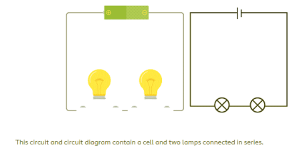
- When components like a battery, motor, lamp, switch, or wire are connected in series, they form a single loop where each component is placed one after another, similar to episodes in a TV series.
- The components are linked end-to-end, with the final wire closing the circuit, creating a single path for the current (I) to flow. Current, which is the flow of charges, is measured in amps (A).
- In a series circuit, if a lamp breaks or a component is disconnected, the entire circuit is interrupted, causing all components to stop working.
- Current ceases to flow in the circuit because the loop is no longer complete, preventing the current from circulating.
- Switches can be incorporated into a series circuit to control the components, turning them on or off.
- If any switch in a series circuit is open, the current stops flowing, causing all components to stop working.
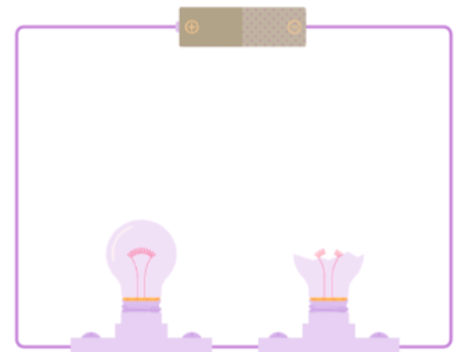 If one component in a series circuit breaks, all the components stop working because current stops flowing.
Current and Resistance in Series Circuits
- Current (I) is the flow of charges measured in amperes (A).
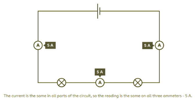
- In a series circuit, current has the same value throughout the circuit.
- Regardless of where the ammeter is placed in a series circuit, it will show the same reading.
- Series circuits involve connecting components in a single loop with only one path for current to flow.
- Example of Current in Series Circuit:
- In a circuit with a cell, two lamps, and three ammeters, all ammeters display the same reading due to the single path for current flow.
Adding Components in Series
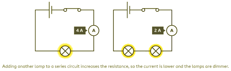
- When components are added in series in a circuit, the total resistance increases. Consequently, the flow of current decreases.
- In a circuit with a single lamp, a cell, a switch, and an ammeter, a current of 4 A is observed.
- When two lamps are added to the circuit along with the cell, switch, and ammeter, the total resistance increases. As a result, the current reduces to 2 A. This decrease in current leads to dimmer light emitted by the lamps.
Potential difference in series circuits
- The potential difference generated by a cell or battery is distributed among the components in a series circuit.
- The sum of the potential differences across each component equals the total potential difference of the cell or battery.
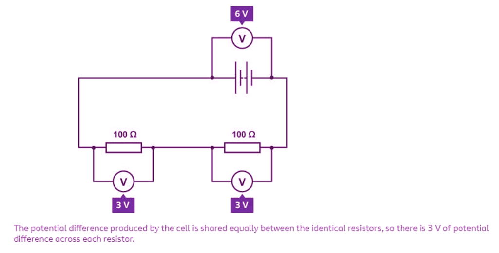
- In a circuit with a 6 V battery and two 100 Ω resistors in series, voltmeters connected across the battery and components measure the potential difference.
- Since the resistors are identical, the potential difference across each resistor is 3 V, dividing equally between them.
- If the components in a series circuit have different resistances, the potential difference divides unequally across them.
Question for Series CircuitsTry yourself: What happens to the current in a series circuit when components are added?View Solution
Resistors in Series
- If resistor A component which resists the flow of current. are placed in series in a circuit, the overall resistance (R) increases. This means that it becomes more difficult for current to flow through the circuit.
- When resistors are connected in series, their resistances add up to give the total resistance of the circuit. For example, if you have a 5Ω resistor and a 10Ω resistor connected in series, the total resistance would be 15Ω.
- Series circuits have the same current passing through each component. This implies that the current remains constant throughout the circuit. For instance, if you have a series circuit with a 2A current passing through it, every component in the circuit will also have a 2A current flowing through it.
- One key aspect of resistors in series is that if one resistor fails or is removed, it can interrupt the flow of current through the entire circuit. This is because removing a component from a series circuit creates an open circuit, preventing the flow of electricity.
Resistors in Parallel
- When resistors are connected in parallel in a circuit, the total resistance of the circuit decreases. This is because the current has multiple paths to follow, reducing the overall resistance compared to when the resistors are in series.
- In a parallel circuit, each resistor has the full circuit voltage applied to it. This means that if you have a 12V battery connected to three parallel resistors, each resistor will have 12V across it.
- Parallel circuits have the same voltage across each branch. If you measure the voltage across each resistor in a parallel circuit, you will find that it is the same across all of them. This is because each branch in a parallel circuit is connected across the same voltage source.
- If one resistor fails in a parallel circuit, the other components will continue to operate as they are on separate branches. Unlike in series circuits, where a single component failure can disrupt the entire circuit, parallel circuits offer redundancy in operation.
FAQs on Series Circuits - Year 7
| 1. What are the key points to consider in electric circuits? |  |
Ans. The key points to consider in electric circuits include understanding potential difference, circuit breaks and switches, current and resistance in series circuits, and how components are connected in series.
| 2. How can components be connected in series circuits? | |
Ans. Components in series circuits are connected one after the other, forming a single pathway for the current to flow through each component in order.
| 3. What is the significance of potential difference in series circuits? | |
Ans. Potential difference in series circuits is the total energy used by the components in the circuit, and it is shared among all the components based on their resistance.
| 4. What role do circuit breaks and switches play in electric circuits? | |
Ans. Circuit breaks and switches are used to control the flow of electricity in a circuit. Circuit breaks are designed to automatically interrupt the flow of current in case of an overload or short circuit, while switches allow for manual control of the circuit.
| 5. How does current and resistance affect series circuits? | |
Ans. Current is the flow of electric charge through a circuit, and resistance is the opposition to this flow. In series circuits, the total resistance is the sum of the individual resistances, and the current is the same throughout the circuit.
About this Document

4.85/5
Rating

Oct 10, 2025
Last updated
Related Exams
Document Description: Series Circuits for Year 7 2025 is part of Year 7 preparation. The notes and questions for Series Circuits have been prepared according to the Year 7 exam syllabus. Information about Series Circuits covers topics like Introduction, Connecting components in series, Current and Resistance in Series Circuits, Adding Components in Series, Potential difference in series circuits, Resistors in Series, Resistors in Parallel and Series Circuits Example, for Year 7 2025 Exam. Find important definitions, questions, notes, meanings, examples, exercises and tests below for Series Circuits.
Description
Full syllabus notes, lecture & questions for Series Circuits - Year 7 - Year 7 | Plus excerises question with solution to help you revise complete syllabus | Best notes, free PDF download
Information about Series Circuits
In this doc you can find the meaning of Series Circuits defined & explained in the simplest way possible.
Besides explaining types of Series Circuits theory,
EduRev gives you an ample number of questions to practice Series Circuits tests, examples and also practice Year 7 tests.
Related Searches
ppt
,Series Circuits - Year 7
,MCQs
,past year papers
,Free
,Exam
,study material
,Extra Questions
,Semester Notes
,mock tests for examination
,Viva Questions
,video lectures
,Important questions
,Summary
,Sample Paper
,Previous Year Questions with Solutions
,practice quizzes
,Series Circuits - Year 7
,Series Circuits - Year 7
,shortcuts and tricks
,Objective type Questions
;


Additional Information about Series Circuits for Year 7 Preparation
Series Circuits Free PDF Download
The Series Circuits is an invaluable resource that delves deep into the core of the Year 7 exam.
These study notes are curated by experts and cover all the essential topics and concepts, making your preparation more efficient and effective.
With the help of these notes, you can grasp complex subjects quickly, revise important points easily,
and reinforce your understanding of key concepts. The study notes are presented in a concise and easy-to-understand manner,
allowing you to optimize your learning process. Whether you're looking for best-recommended books, sample papers, study material,
or toppers' notes, this PDF has got you covered. Download the Series Circuits now and kickstart your journey towards success in the Year 7 exam.
Importance of Series Circuits
The importance of Series Circuits cannot be overstated, especially for Year 7 aspirants.
This document holds the key to success in the Year 7 exam.
It offers a detailed understanding of the concept, providing invaluable insights into the topic.
By knowing the concepts well in advance, students can plan their preparation effectively.
Utilize this indispensable guide for a well-rounded preparation and achieve your desired results.
Series Circuits Notes
Series Circuits Notes offer in-depth insights into the specific topic to help you master it with ease.
This comprehensive document covers all aspects related to Series Circuits.
It includes detailed information about the exam syllabus, recommended books, and study materials for a well-rounded preparation.
Practice papers and question papers enable you to assess your progress effectively.
Additionally, the paper analysis provides valuable tips for tackling the exam strategically.
Access to Toppers' notes gives you an edge in understanding complex concepts.
Whether you're a beginner or aiming for advanced proficiency, Series Circuits Notes on EduRev are your ultimate resource for success.
Series Circuits Year 7 Questions
The "Series Circuits Year 7 Questions" guide is a valuable resource for all aspiring students preparing for the
Year 7 exam. It focuses on providing a wide range of practice questions to help students gauge
their understanding of the exam topics. These questions cover the entire syllabus, ensuring comprehensive preparation.
The guide includes previous years' question papers for students to familiarize themselves with the exam's format and difficulty level.
Additionally, it offers subject-specific question banks, allowing students to focus on weak areas and improve their performance.
Study Series Circuits on the App
Students of Year 7 can study Series Circuits alongwith tests & analysis from the EduRev app,
which will help them while preparing for their exam. Apart from the Series Circuits,
students can also utilize the EduRev App for other study materials such as previous year question papers, syllabus, important questions, etc.
The EduRev App will make your learning easier as you can access it from anywhere you want.
The content of Series Circuits is prepared as per the latest Year 7 syllabus.
|
© EduRev
|
Education Revolution
|


|


Signup to see your scores
go up
within 7 days!
within 7 days!
Takes less than 10 seconds to signup