Q21: Assuming an ideal transformer, the Thevenin's equivalent voltage and impedance as seen from the terminals x and y for the circuit in figure are (SET-2 (2014))
 (a) 2sin(ωt), 4Ω
(b) 1sin(ωt), 1Ω
(c) 1sin(ωt), 2Ω
(d) 2sin(ωt), 0.5Ω
Ans: (a)
Sol: Thevenin's equivalent voltage = voltage referred to secondary.
We have: 
VTh = 2sin(ωt)
 Also, Thevenin's impedance seen from the x and y terminals = voltage referred to secondary side

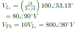
Q22: In the circuit shown below, if the source voltage Vs = 100∠53.13°V then the Thevenin's equivalent voltage in Volts as seen by the load resistance RL is (2013)
 (a) 100 ∠ 90°
(b) 800 ∠ 0°
(c) 800 ∠ 90∘
(d) 100 ∠ 60∘
Ans: (c)
Sol: 
Q23: A source vs(t) = Vcos 100πt has an internal impedance of (4 + j3)Ω. If a purely resistive load connected to this source has to extract the maximum power out of the source, its value in Ω should be (2013)
(a) 3
(b) 4
(c) 5
(d) 7
Ans: (c)
Sol: Using maximum power transfer theorem,

Q24: Assuming both the voltage sources are in phase, the value of R for which maximum power is transferred from circuit A to circuit B is (2012)
 (a) 0.8 Ω
(b) 1.4 Ω
(c) 2 Ω
(d) 2.8 Ω
Ans: (a)
Sol: 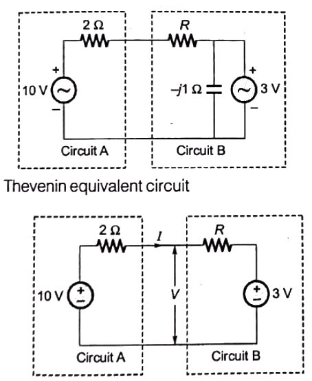
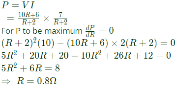
 Power transferred from circuit A to circuit B
Q25: The impedance looking into nodes 1 and 2 in the given circuit is (2012)
 (a) 50 Ω
(b) 100 Ω
(c) 5 kΩ
(d) 10.1 kΩ
Ans: (a)
Sol:  To find thevenin impedance across node 1 and node 2. Connect a 1 V source and find the current through voltage source.
Then, ZTh = 1/(ITh)
By applying KCL at node B and A
 By applying KVL in outer loop
 ∴ From equation (i),

Q26: In the circuit given below, the value of R required for the transfer of maximum power to the load having a resistance of 3 Ω is (2011)
 (a) zero
(b) 3Ω
(c) 6Ω
(d) infinity
Ans: (a)
Sol:  For maximum power transfer to the load, the source resistance must be minimum i.e. zero.
So, R = 0Ω.
Q27:  For the circuit given above, the Thevenin's voltage across the terminals A and B is (2009)
(a) 1.25V
(b) 0.25V
(c) 1V
(d) 0.5V
Ans: (d)
Sol:  To calculate thevenin's volatage, terminal A-B are kept open.
Applying source transformation, voltage sorce is transformed into current source.
 Applying source transformation current source is transformed into voltage souce.
 Applying KVL, (I is assumed to be in mA)
 Put value of I in equation (i),

Q28:  For the circuit given above, the Thevenin's resistance across the terminals A and B is (2009)
(a) 0.5 kΩ
(b) 0.2 kΩ
(c) 1 kΩ
(d) 0.11 kΩ
Ans: (b)
Sol: To calculate thevenin's resistance 5 V source is short-circuited and Vdc source is connected at terminals A and B
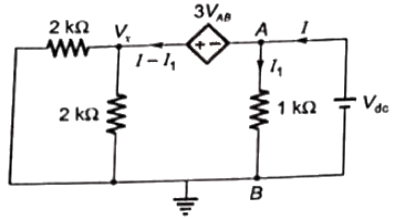
 VAB = Vdc and assuming I and I1 in mA. Current through 1kΩ resistance
 Comparing equation (i) and (ii),

Q29: The Thevenin's equivalent of a circuit operation at ω = 5 rads/s, has Voc = 3.71∠ − 15.9° V and Z0 = 2.38 − j0.667Ω. At this frequency, the minimal realization of the Thevenin's impedance will have a (2008)
(a) resistor and a capacitor and an inductor
(b) resistor and a capacitor
(c) resistor and an inductor
(d) capacitor and an inductor
Ans: (b)
Sol: Thevenin's Impedance:
 as real part is not zero, so Z0 has resistor
Img[Z0] = −j0.667
CASE-I:
Z0 has capacitor (as Img[Z0] is negative)
CASE-II:
Z0 has both capacitor and inductor, but inductive reactance < capacitive reactance.
At, ω = 5 rad/sec
For minimal realization case-I is considered. Therefore, Z0 will have a resistor and a capacitor.
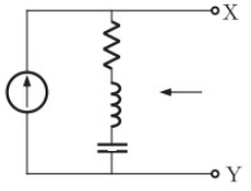
Q30: In the figure the current source is 1 ∠ 0 A, R = 1 Ω, the impedances are ZC = −jΩ and ZL= 2jΩ. The Thevenin equivalent looking into the circuit across X-Y is (2006)
(a) 
(b) 
(c) 
(d) 
Ans: (d)
Sol: To calculate Thevenin's impedance, current-souce is open-circuited
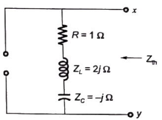
 Open-circuit voltage at terminals X - Y

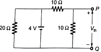
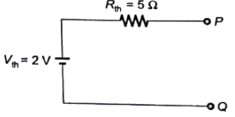
Q31: In the given figure, the Thevenin's equivalent pair (voltage, impedance), as seen at the terminals P-Q, is given by (2005)
 (a) (2V, 5Ω)
(b) (2V, 7.5Ω)
(c) (4V, 5Ω)
(d) (4V, 7.5Ω)
Ans: (a)
Sol: To calculate Rth (seen at terminals P-Q), voltage source is short-circuit
 Vth = open-circuit voltage at terminals P-Q.
 Thevenin's equivalent circuit
Q32: Two ac sources feed a common variable resistive load as shown in figure. Under the maximum power transfer condition, the power absorbed by the load resistance RL is (2003)
 (a) 2200 W
(b) 1250 W
(c) 1000 W
(d) 625 W
Ans: (d)
Sol: For obtaining power absorbed by RL under maximum power transfer condition. We find thevenin's equivalent circuit across RL.
 Zth is calculated by short-circuting the voltage source.

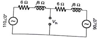

 For maximum power transfer ,
 Power absorbed by RL(max)

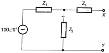
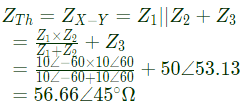
Q33: In the figure, Z1 = 10∠ − 60°, Z2 = 10∠60°, Z3 = 50∠53.13°. The venin impedance seen form X-Y is (2003)
 (a) 56.66 ∠ 45°
(b) 60 ∠ 30°
(c) 70 ∠ 30°
(d) 34.4 ∠ 65°
Ans: (a)
Sol: By Thevenin's theorem
Q34: In the circuit shown in figure, the switch is closed at time t = 0. The steady state value of the voltage Vc is (2002)
 (a) 0 V
(b) 10 V
(c) 5 V
(d) 2.5 V
Ans: (c)
Q35: A 240 V single-phase ac source is connected to a load with an impedance of 10∠60°Ω. A capacitor is connected in parallel with the load. If the capacitor supplies 1250 VAR, the real power supplied by the source is (2001)
(a) 3600 W
(b) 2880 W
(c) 2400 W
(d) 1200 W
Ans: (b)
 (a) 2sin(ωt), 4Ω
 Also, Thevenin's impedance seen from the x and y terminals = voltage referred to secondary side
 (a) 100 ∠ 90°


 (a) 0.8 Ω
 Power transferred from circuit A to circuit B
 (a) 50 Ω
 To find thevenin impedance across node 1 and node 2. Connect a 1 V source and find the current through voltage source.
 By applying KVL in outer loop
 ∴ From equation (i),
 (a) zero
 For maximum power transfer to the load, the source resistance must be minimum i.e. zero.
 For the circuit given above, the Thevenin's voltage across the terminals A and B is (2009)
 To calculate thevenin's volatage, terminal A-B are kept open.
 Applying source transformation current source is transformed into voltage souce.
 Applying KVL, (I is assumed to be in mA)
 Put value of I in equation (i),
 For the circuit given above, the Thevenin's resistance across the terminals A and B is (2009)
 VAB = Vdc and assuming I and I1 in mA. Current through 1kΩ resistance
 Comparing equation (i) and (ii),
 as real part is not zero, so Z0 has resistor


 Open-circuit voltage at terminals X - Y
 (a) (2V, 5Ω)
 Vth = open-circuit voltage at terminals P-Q.
 Thevenin's equivalent circuit
 (a) 2200 W
 Zth is calculated by short-circuting the voltage source.


 For maximum power transfer ,
 Power absorbed by RL(max)
 (a) 56.66 ∠ 45°

 (a) 0 V


