Electrical Engineering (EE) Exam  >  Electrical Engineering (EE) Notes  >  Network Theory (Electric Circuits)  >  Previous Year Questions- Transients and Steady State Response - 1

Previous Year Questions- Transients and Steady State Response - 1 | Network Theory (Electric Circuits) - Electrical Engineering (EE) PDF Download

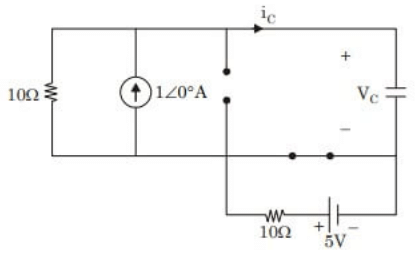
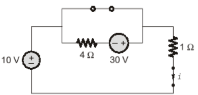
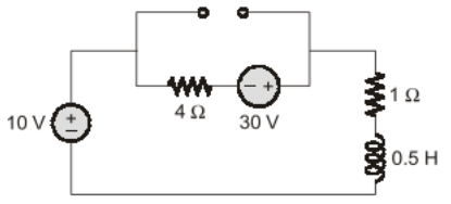
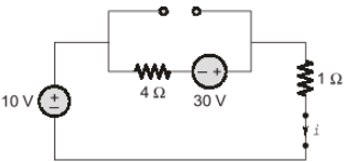
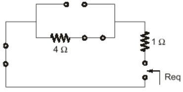
Q1: The circuit shown in the figure with the switch S open, is in steady state. After the switch S is closed, the time constant of the circuit in seconds is     (2024)
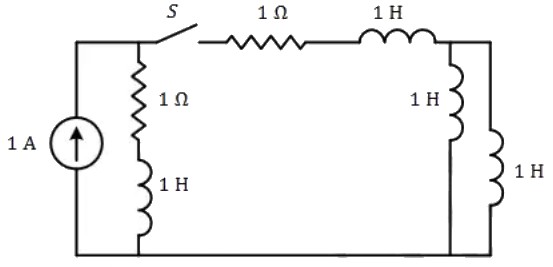
Previous Year Questions- Transients and Steady State Response - 1 | Network Theory (Electric Circuits) - Electrical Engineering (EE)(a) 1.25
(b) 0
(c) 1
(d) 1.5
Ans:
(a)
Sol: Previous Year Questions- Transients and Steady State Response - 1 | Network Theory (Electric Circuits) - Electrical Engineering (EE)
Q2: The circuit shown in the figure is initially in the steady state with the switch K in open condition and Previous Year Questions- Transients and Steady State Response - 1 | Network Theory (Electric Circuits) - Electrical Engineering (EE) in closed condition. The switch K is closed and Previous Year Questions- Transients and Steady State Response - 1 | Network Theory (Electric Circuits) - Electrical Engineering (EE) is opened simultaneously at the instant t = t1, where t> 0. The minimum value of t1 in milliseconds, such that there is no transient in the voltage across the 100μF capacitor, is ___ (Round off to 2 decimal places).      (2023)
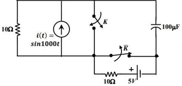
Previous Year Questions- Transients and Steady State Response - 1 | Network Theory (Electric Circuits) - Electrical Engineering (EE)(a) 0.87
(b) 1.57
(c) 1.88
(d) 2.26
Ans:
(b)
Sol: Switch K is open and Previous Year Questions- Transients and Steady State Response - 1 | Network Theory (Electric Circuits) - Electrical Engineering (EE) is closed.
Redraw the circuit :
Previous Year Questions- Transients and Steady State Response - 1 | Network Theory (Electric Circuits) - Electrical Engineering (EE)From circuit, using current division,
Previous Year Questions- Transients and Steady State Response - 1 | Network Theory (Electric Circuits) - Electrical Engineering (EE)Previous Year Questions- Transients and Steady State Response - 1 | Network Theory (Electric Circuits) - Electrical Engineering (EE)Case (ii) :
Switch K is closed andPrevious Year Questions- Transients and Steady State Response - 1 | Network Theory (Electric Circuits) - Electrical Engineering (EE)  is open.
Current source and 10Ω resistor becomes short circuited.
Redraw the circuit :
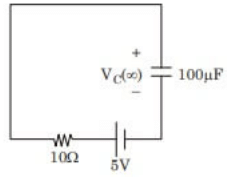
Previous Year Questions- Transients and Steady State Response - 1 | Network Theory (Electric Circuits) - Electrical Engineering (EE)From circuit,
Previous Year Questions- Transients and Steady State Response - 1 | Network Theory (Electric Circuits) - Electrical Engineering (EE)Previous Year Questions- Transients and Steady State Response - 1 | Network Theory (Electric Circuits) - Electrical Engineering (EE)We have,
Previous Year Questions- Transients and Steady State Response - 1 | Network Theory (Electric Circuits) - Electrical Engineering (EE)For transient free voltage,
Previous Year Questions- Transients and Steady State Response - 1 | Network Theory (Electric Circuits) - Electrical Engineering (EE)Previous Year Questions- Transients and Steady State Response - 1 | Network Theory (Electric Circuits) - Electrical Engineering (EE)
Q3: In the circuit shown below, the switch S is closed at t = 0. The magnitude of the steady state voltage, in volts, across the 6Ω resistor is _________. (round off to two decimal places).       (2022)
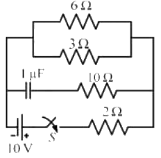
Previous Year Questions- Transients and Steady State Response - 1 | Network Theory (Electric Circuits) - Electrical Engineering (EE)(a) 5
(b) 8.25
(c) 12.55
(d) 3.35
Ans:
(a)
Sol: Concept: At steady state, capacitor behaves as open circuit. 
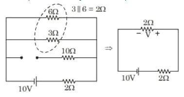
Previous Year Questions- Transients and Steady State Response - 1 | Network Theory (Electric Circuits) - Electrical Engineering (EE)Using voltage division,
Previous Year Questions- Transients and Steady State Response - 1 | Network Theory (Electric Circuits) - Electrical Engineering (EE)
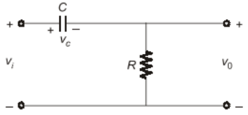
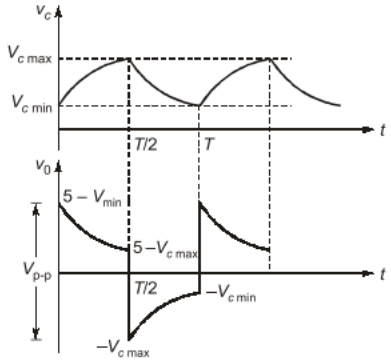
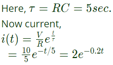
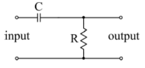
Q4: A 100 Hz square wave, switching between 0 V and 5 V, is applied to a CR high-pass filter circuit as shown. The output voltage waveform across the resistor is 6.2 V peak-to-peak. If the resistance R is 820 Ω, then the value C is ______________ μF. (Round off to 2 decimal places.)      (2021)
Previous Year Questions- Transients and Steady State Response - 1 | Network Theory (Electric Circuits) - Electrical Engineering (EE)(a) 18.5
(b) 12.46
(c) 10.06
(d) 15.48
Ans:
(b)
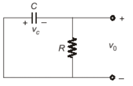
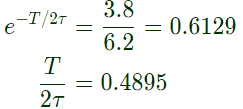
Sol: Previous Year Questions- Transients and Steady State Response - 1 | Network Theory (Electric Circuits) - Electrical Engineering (EE)Previous Year Questions- Transients and Steady State Response - 1 | Network Theory (Electric Circuits) - Electrical Engineering (EE)Previous Year Questions- Transients and Steady State Response - 1 | Network Theory (Electric Circuits) - Electrical Engineering (EE)Previous Year Questions- Transients and Steady State Response - 1 | Network Theory (Electric Circuits) - Electrical Engineering (EE)Previous Year Questions- Transients and Steady State Response - 1 | Network Theory (Electric Circuits) - Electrical Engineering (EE)Previous Year Questions- Transients and Steady State Response - 1 | Network Theory (Electric Circuits) - Electrical Engineering (EE)Previous Year Questions- Transients and Steady State Response - 1 | Network Theory (Electric Circuits) - Electrical Engineering (EE)Previous Year Questions- Transients and Steady State Response - 1 | Network Theory (Electric Circuits) - Electrical Engineering (EE)Previous Year Questions- Transients and Steady State Response - 1 | Network Theory (Electric Circuits) - Electrical Engineering (EE)Previous Year Questions- Transients and Steady State Response - 1 | Network Theory (Electric Circuits) - Electrical Engineering (EE)Previous Year Questions- Transients and Steady State Response - 1 | Network Theory (Electric Circuits) - Electrical Engineering (EE)Previous Year Questions- Transients and Steady State Response - 1 | Network Theory (Electric Circuits) - Electrical Engineering (EE)Previous Year Questions- Transients and Steady State Response - 1 | Network Theory (Electric Circuits) - Electrical Engineering (EE)Previous Year Questions- Transients and Steady State Response - 1 | Network Theory (Electric Circuits) - Electrical Engineering (EE)Previous Year Questions- Transients and Steady State Response - 1 | Network Theory (Electric Circuits) - Electrical Engineering (EE)Previous Year Questions- Transients and Steady State Response - 1 | Network Theory (Electric Circuits) - Electrical Engineering (EE)Previous Year Questions- Transients and Steady State Response - 1 | Network Theory (Electric Circuits) - Electrical Engineering (EE)From (ii),
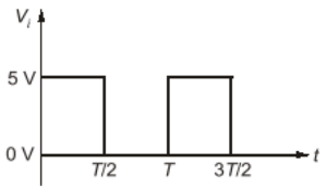
Previous Year Questions- Transients and Steady State Response - 1 | Network Theory (Electric Circuits) - Electrical Engineering (EE)Previous Year Questions- Transients and Steady State Response - 1 | Network Theory (Electric Circuits) - Electrical Engineering (EE)Previous Year Questions- Transients and Steady State Response - 1 | Network Theory (Electric Circuits) - Electrical Engineering (EE)Using equation (iii)
Previous Year Questions- Transients and Steady State Response - 1 | Network Theory (Electric Circuits) - Electrical Engineering (EE)Previous Year Questions- Transients and Steady State Response - 1 | Network Theory (Electric Circuits) - Electrical Engineering (EE)
Previous Year Questions- Transients and Steady State Response - 1 | Network Theory (Electric Circuits) - Electrical Engineering (EE)Previous Year Questions- Transients and Steady State Response - 1 | Network Theory (Electric Circuits) - Electrical Engineering (EE)as Previous Year Questions- Transients and Steady State Response - 1 | Network Theory (Electric Circuits) - Electrical Engineering (EE)and Previous Year Questions- Transients and Steady State Response - 1 | Network Theory (Electric Circuits) - Electrical Engineering (EE)Previous Year Questions- Transients and Steady State Response - 1 | Network Theory (Electric Circuits) - Electrical Engineering (EE)
∴ C = 12.46 μF

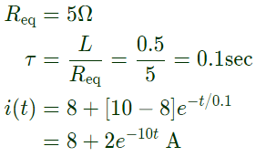
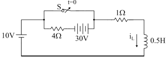
Q5: In the circuit, switch 'S' is in the closed position for a very long time. If the switch is opened at time t = 0, then in iL(t) amperes, for t ≥ 0 is      (2021)
Previous Year Questions- Transients and Steady State Response - 1 | Network Theory (Electric Circuits) - Electrical Engineering (EE)(a) 8e-10t
(b) 10
(c) 8 + 2e-10t
(d) 10(1 - e-2t)
Ans:
(c)
Sol: Previous Year Questions- Transients and Steady State Response - 1 | Network Theory (Electric Circuits) - Electrical Engineering (EE)Previous Year Questions- Transients and Steady State Response - 1 | Network Theory (Electric Circuits) - Electrical Engineering (EE)Previous Year Questions- Transients and Steady State Response - 1 | Network Theory (Electric Circuits) - Electrical Engineering (EE)Previous Year Questions- Transients and Steady State Response - 1 | Network Theory (Electric Circuits) - Electrical Engineering (EE)At t = ∞
Previous Year Questions- Transients and Steady State Response - 1 | Network Theory (Electric Circuits) - Electrical Engineering (EE)Previous Year Questions- Transients and Steady State Response - 1 | Network Theory (Electric Circuits) - Electrical Engineering (EE)Previous Year Questions- Transients and Steady State Response - 1 | Network Theory (Electric Circuits) - Electrical Engineering (EE)Previous Year Questions- Transients and Steady State Response - 1 | Network Theory (Electric Circuits) - Electrical Engineering (EE)
Q6: The initial charge in the 1 F capacitor present in the circuit shown is zero. The energy in joules transferred from the DC source until steady state condition is reached equals ______. (Give the answer up to one decimal place.)      (SET-2 (2017))
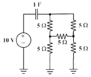
Previous Year Questions- Transients and Steady State Response - 1 | Network Theory (Electric Circuits) - Electrical Engineering (EE)(a) 100
(b) 200
(c) 50
(d) 400
Ans:
(a)
Sol: Consider the following circuit diagram,
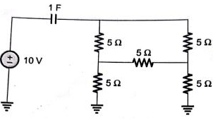
Previous Year Questions- Transients and Steady State Response - 1 | Network Theory (Electric Circuits) - Electrical Engineering (EE)After minimizing circuit elements we can have the following circuit,
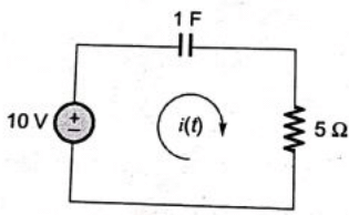
Previous Year Questions- Transients and Steady State Response - 1 | Network Theory (Electric Circuits) - Electrical Engineering (EE)Previous Year Questions- Transients and Steady State Response - 1 | Network Theory (Electric Circuits) - Electrical Engineering (EE)Energy supplied by the source,
Previous Year Questions- Transients and Steady State Response - 1 | Network Theory (Electric Circuits) - Electrical Engineering (EE)
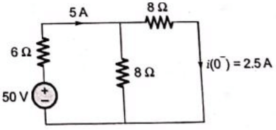
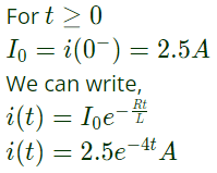
Q7: The switch in the figure below was closed for a long time. It is opened at t = 0. The current in the inductor of 2 H for t ≥ 0, is     (SET-1 (2017))
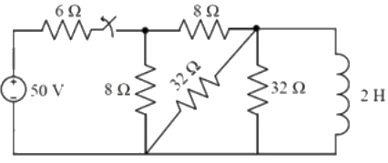
Previous Year Questions- Transients and Steady State Response - 1 | Network Theory (Electric Circuits) - Electrical Engineering (EE)(a) 2.5 e-4t
(b) 5e-4t
(c) 2.5e-0.25t
(d) 5e-0.25t
Ans:
(a)
Sol: From the given circuit, consider the following circuit diagram,
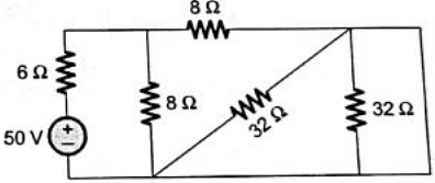
Previous Year Questions- Transients and Steady State Response - 1 | Network Theory (Electric Circuits) - Electrical Engineering (EE)After rearrangement
Previous Year Questions- Transients and Steady State Response - 1 | Network Theory (Electric Circuits) - Electrical Engineering (EE)Previous Year Questions- Transients and Steady State Response - 1 | Network Theory (Electric Circuits) - Electrical Engineering (EE)
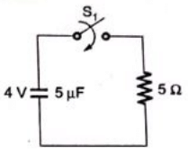
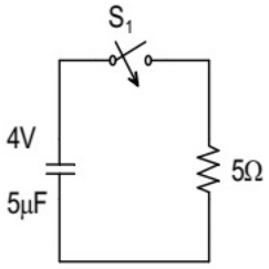
Q8: In the circuit shown below, the initial capacitor voltage is 4 V. Switch S1 is closed at t = 0. The charge (in μC) lost by the capacitor from t = 25 μs to t = 100 μs is ____________.        (SET-2(2016))
Previous Year Questions- Transients and Steady State Response - 1 | Network Theory (Electric Circuits) - Electrical Engineering (EE)(a) 5
(b) 6
(c) 7
(d) 8
Ans:
(c)
Sol: Previous Year Questions- Transients and Steady State Response - 1 | Network Theory (Electric Circuits) - Electrical Engineering (EE)Previous Year Questions- Transients and Steady State Response - 1 | Network Theory (Electric Circuits) - Electrical Engineering (EE)Change lost by capacitor from t = 25 μs to 100 μs is
Previous Year Questions- Transients and Steady State Response - 1 | Network Theory (Electric Circuits) - Electrical Engineering (EE)
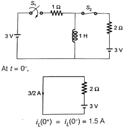
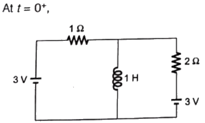
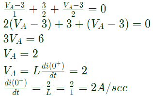
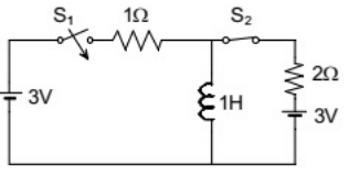
Q9: In the circuit shown, switch S2 has been closed for a long time. At time t = 0 switch  S1 is closed. At  t = 0+, the rate of change of current through the inductor, in amperes per second, is _____.      (SET-1 (2016))
Previous Year Questions- Transients and Steady State Response - 1 | Network Theory (Electric Circuits) - Electrical Engineering (EE)(a) 1
(b) 2
(c) 3
(d) 4
Ans:
(b)
Sol: Previous Year Questions- Transients and Steady State Response - 1 | Network Theory (Electric Circuits) - Electrical Engineering (EE)Previous Year Questions- Transients and Steady State Response - 1 | Network Theory (Electric Circuits) - Electrical Engineering (EE)KCL at node A,
Previous Year Questions- Transients and Steady State Response - 1 | Network Theory (Electric Circuits) - Electrical Engineering (EE)
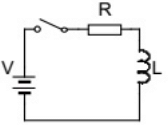
Q10: A series RL circuit is excited at t = 0 by closing a switch as shown in the figure. Assuming zero initial conditions, the value of Previous Year Questions- Transients and Steady State Response - 1 | Network Theory (Electric Circuits) - Electrical Engineering (EE) is       (SET-2 (2015))
Previous Year Questions- Transients and Steady State Response - 1 | Network Theory (Electric Circuits) - Electrical Engineering (EE)(a) V/L
(b) (-V)/R
(c) 0
(d) (-RV)/(L2)
Ans:
(d)
Sol: Previous Year Questions- Transients and Steady State Response - 1 | Network Theory (Electric Circuits) - Electrical Engineering (EE)Initially (t = 0) the inductor would be uncharged.
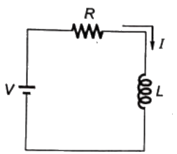
So, I(0+) = 0  
The KVL in th loop will be
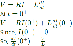
Previous Year Questions- Transients and Steady State Response - 1 | Network Theory (Electric Circuits) - Electrical Engineering (EE)Now, lets differentiate the above equation
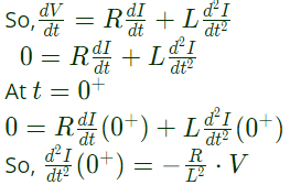
Previous Year Questions- Transients and Steady State Response - 1 | Network Theory (Electric Circuits) - Electrical Engineering (EE)
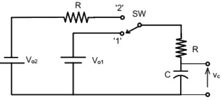
Q11: The switch SW shown in the circuit is kept at position '1' for a long duration. At t = 0+, the switch is moved to position '2'. Assuming ∣Vo2∣ > ∣Vo1∣, the voltage vc(t) across the capacitor is      (SET-2 (2014))
Previous Year Questions- Transients and Steady State Response - 1 | Network Theory (Electric Circuits) - Electrical Engineering (EE)(a) Previous Year Questions- Transients and Steady State Response - 1 | Network Theory (Electric Circuits) - Electrical Engineering (EE)

(b) Previous Year Questions- Transients and Steady State Response - 1 | Network Theory (Electric Circuits) - Electrical Engineering (EE)
(c) Previous Year Questions- Transients and Steady State Response - 1 | Network Theory (Electric Circuits) - Electrical Engineering (EE)
(d) Previous Year Questions- Transients and Steady State Response - 1 | Network Theory (Electric Circuits) - Electrical Engineering (EE)
Ans: (d)

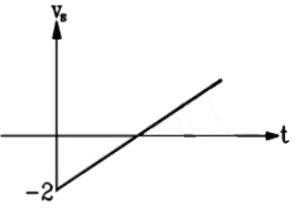
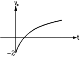
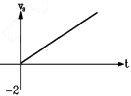
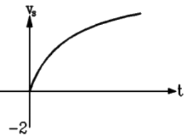
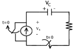
Q12: A combination of 1 μF capacitor with an initial voltage vc(0) = −2V in series with a 100 Ω resistor is connected to a 20 mA ideal dc current source by operating both switches at t = 0s as shown. Which of the following graphs shown in the options approximates the voltage  vs across the current source over the next few seconds ?      (SET-1  (2014))
Previous Year Questions- Transients and Steady State Response - 1 | Network Theory (Electric Circuits) - Electrical Engineering (EE)(a) Previous Year Questions- Transients and Steady State Response - 1 | Network Theory (Electric Circuits) - Electrical Engineering (EE)(b) Previous Year Questions- Transients and Steady State Response - 1 | Network Theory (Electric Circuits) - Electrical Engineering (EE)(c) Previous Year Questions- Transients and Steady State Response - 1 | Network Theory (Electric Circuits) - Electrical Engineering (EE)(d) Previous Year Questions- Transients and Steady State Response - 1 | Network Theory (Electric Circuits) - Electrical Engineering (EE)Ans:
(c)
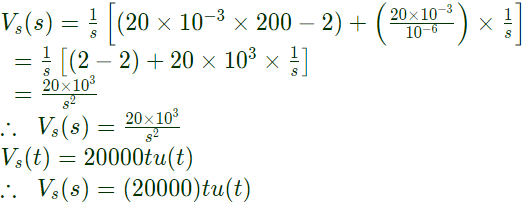
Sol: Given C =1μF, Vc(0) = −2V,  R= 100Ω, I = 20mA. Circuit fot the given condition at time t > 0 is shown below:
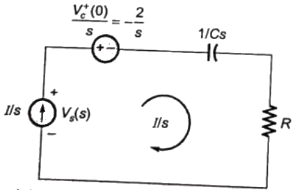
Previous Year Questions- Transients and Steady State Response - 1 | Network Theory (Electric Circuits) - Electrical Engineering (EE)Applying KVL, we have, Previous Year Questions- Transients and Steady State Response - 1 | Network Theory (Electric Circuits) - Electrical Engineering (EE)Previous Year Questions- Transients and Steady State Response - 1 | Network Theory (Electric Circuits) - Electrical Engineering (EE)Putting values of R, C and I, we get,
Previous Year Questions- Transients and Steady State Response - 1 | Network Theory (Electric Circuits) - Electrical Engineering (EE)Which is equation of a straight line passing through origin. Hence option (C) is correct.

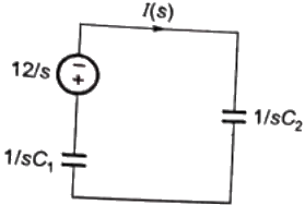
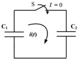
Q13: In the following figure, C1 and C2 are ideal capacitors. C1 has been charged to 12 V before the ideal switch S is closed at t = 0. The current i(t) for all t is     (2012)
Previous Year Questions- Transients and Steady State Response - 1 | Network Theory (Electric Circuits) - Electrical Engineering (EE)(a) zero
(b) a step function
(c) an exponentially decaying function
(d) an impulse function
Ans:
(d)
Sol: Previous Year Questions- Transients and Steady State Response - 1 | Network Theory (Electric Circuits) - Electrical Engineering (EE)Circuit is s-domain
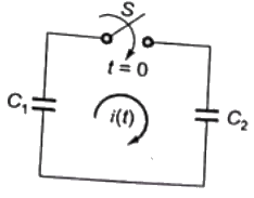
Previous Year Questions- Transients and Steady State Response - 1 | Network Theory (Electric Circuits) - Electrical Engineering (EE)By applying KVL,
Previous Year Questions- Transients and Steady State Response - 1 | Network Theory (Electric Circuits) - Electrical Engineering (EE)∴ Current i(t) is an implulse function.

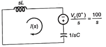
Q14: The L-C circuit shown in the figure has an inductance L = 1mH and a capacitance C =  μF.
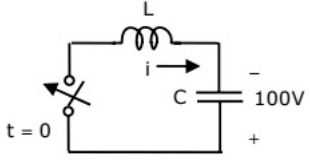
Previous Year Questions- Transients and Steady State Response - 1 | Network Theory (Electric Circuits) - Electrical Engineering (EE)The initial current through the inductor is zero, while the initial capacitor voltage is 100 V. The switch is closed at t = 0. The current i through the circuit      (2010)
(a) 5𝑐𝑜𝑠(5×10³𝑡)𝐴5cos(5 × 10³t)A
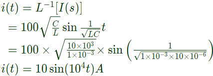
(b) 10sin(104t)A  
(c) 10𝑐𝑜𝑠(5×10³𝑡)𝐴10cos(5 × 10³t)A
(d) 10sin(104t)A
Ans:
(d)
Sol: Initial current through the inductor is zeroand capacitor voltage is charged upto voltage Vc(0) = 100V
As current through inductor and voltage across capacitor can not change abruptly
So, after closing the switch,
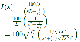
Previous Year Questions- Transients and Steady State Response - 1 | Network Theory (Electric Circuits) - Electrical Engineering (EE)The circuit id s-domain
Previous Year Questions- Transients and Steady State Response - 1 | Network Theory (Electric Circuits) - Electrical Engineering (EE)Previous Year Questions- Transients and Steady State Response - 1 | Network Theory (Electric Circuits) - Electrical Engineering (EE)taking inverse laplace transform
Previous Year Questions- Transients and Steady State Response - 1 | Network Theory (Electric Circuits) - Electrical Engineering (EE)
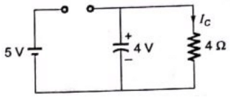
Q15: The switch in the circuit has been closed for a long time. It is opened at t = 0. At t = 0+ , the current through the 1 μF capacitor is       (2010)
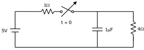
Previous Year Questions- Transients and Steady State Response - 1 | Network Theory (Electric Circuits) - Electrical Engineering (EE)(a) 0A
(b) 1A
(c) 1.25 A
(d) 5A
Ans:
(b)
Sol: As the switch has been closed for a long time, the circuit is in steady state. At steadystate, capacitor is open circuit,
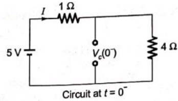
Previous Year Questions- Transients and Steady State Response - 1 | Network Theory (Electric Circuits) - Electrical Engineering (EE)Using KVL,
Previous Year Questions- Transients and Steady State Response - 1 | Network Theory (Electric Circuits) - Electrical Engineering (EE)As the voltage across capacitorcan not change abruptly,
Previous Year Questions- Transients and Steady State Response - 1 | Network Theory (Electric Circuits) - Electrical Engineering (EE)Previous Year Questions- Transients and Steady State Response - 1 | Network Theory (Electric Circuits) - Electrical Engineering (EE)Current through capacitor at t = 0+
Previous Year Questions- Transients and Steady State Response - 1 | Network Theory (Electric Circuits) - Electrical Engineering (EE)

The document Previous Year Questions- Transients and Steady State Response - 1 | Network Theory (Electric Circuits) - Electrical Engineering (EE) is a part of the Electrical Engineering (EE) Course Network Theory (Electric Circuits).
All you need of Electrical Engineering (EE) at this link: Electrical Engineering (EE)
68 videos|85 docs|62 tests

Top Courses for Electrical Engineering (EE)

FAQs on Previous Year Questions- Transients and Steady State Response - 1 - Network Theory (Electric Circuits) - Electrical Engineering (EE)

1. What is the difference between transients and steady-state response in electrical circuits?
Ans. Transients in electrical circuits refer to the temporary behavior of voltages and currents when a circuit is switched on or off, or when there is a sudden change in the input. Steady-state response, on the other hand, is the long-term behavior of voltages and currents after the transients have died down and the circuit has reached a stable operating condition.
2. How do transients affect the performance of electrical circuits?
Ans. Transients can cause voltage spikes, current surges, and other unwanted effects in electrical circuits. These transient effects can potentially damage components, affect the accuracy of measurements, or lead to incorrect operation of the circuit.
3. What are some common methods to analyze transients in electrical circuits?
Ans. Some common methods to analyze transients in electrical circuits include using differential equations to model the circuit, applying Laplace transforms to solve the differential equations, and using simulation software to simulate the transient behavior of the circuit.
4. How can we minimize the impact of transients in electrical circuits?
Ans. To minimize the impact of transients, we can use components like resistors, capacitors, and inductors to dampen the transient effects, employ surge protectors to protect sensitive components from voltage spikes, and ensure proper grounding and shielding of the circuit.
5. Why is it important to understand transients and steady-state response in electrical circuits?
Ans. Understanding transients and steady-state response is crucial for designing reliable and efficient electrical circuits. It helps in predicting and mitigating potential issues caused by transients, ensuring the proper functioning and longevity of the circuit.
68 videos|85 docs|62 tests
Download as PDF
Explore Courses for Electrical Engineering (EE) exam

Top Courses for Electrical Engineering (EE)

Signup for Free!
Signup to see your scores go up within 7 days! Learn & Practice with 1000+ FREE Notes, Videos & Tests.
10M+ students study on EduRev
Related Searches

past year papers

,

MCQs

,

Objective type Questions

,

Free

,

Viva Questions

,

pdf

,

video lectures

,

Important questions

,

Previous Year Questions- Transients and Steady State Response - 1 | Network Theory (Electric Circuits) - Electrical Engineering (EE)

,

shortcuts and tricks

,

study material

,

ppt

,

mock tests for examination

,

Previous Year Questions- Transients and Steady State Response - 1 | Network Theory (Electric Circuits) - Electrical Engineering (EE)

,

Semester Notes

,

practice quizzes

,

Summary

,

Exam

,

Previous Year Questions with Solutions

,

Extra Questions

,

Sample Paper

,

Previous Year Questions- Transients and Steady State Response - 1 | Network Theory (Electric Circuits) - Electrical Engineering (EE)

;