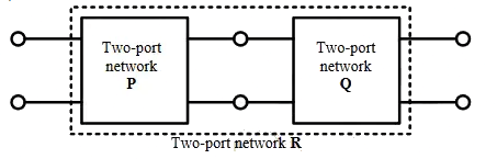
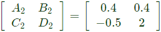
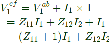
Q1: Two passive two-port network P and Q are connected as shown in the figure. The impedance matrix of network P is 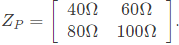 The admittance matrix of network
 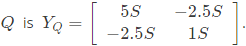 Let the ABCD matrix of the two-port network R in the figure be
  The value of β in Ω is _______ (rounded off to 2 decimal places) (2024)
 (a) -25.36
(b) -19.8
(c) -22.36
(d) -15.25
Ans: (b)
Sol: 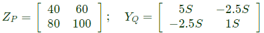 From Zp matrix
 Convert Z-parameters in to ABCD parameters
 From equation (ii),
 Sub equation (iii) in equation (i),
 From equation (iii) and (iv),
 Convert Y-parameters to ABCD parameters From equation (vi),
 Sub equation (vii) in equation (v),
 From equation (vii) and equation (viii),
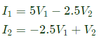
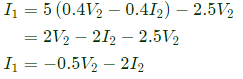
Q2: The admittance parameters of the passive resistive two-port network shown in the figure are
y11 = 5 S, y22 = 1 S, y12 = y21 = -2.5 S
The power delivered to the load resistor RL in Watt is ____ (Round off to 2 decimal places). (2023)
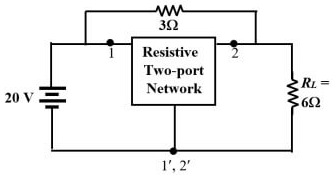 (a) 238
(b) 452.25
(c) 632.12
(d) 145.25
Ans: (a)
Sol: 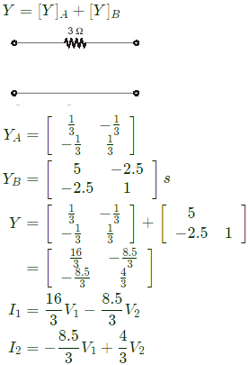
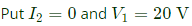
 Equivalent circuit
Q3: In the two-port network shown, the h11 parameter (where, h11= V1/I1, when V2 = 0) in ohms is _____________ (up to 2 decimal places). (2018)
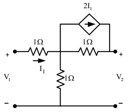 (a) 0.25
(b) 0.5
(c) 0.75
(d) 0.85
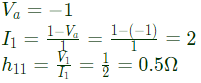
Ans: (b)
Sol: 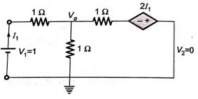 By KCL,
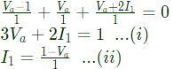 Substitute equation (ii) in equation (i) [/latex]
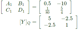
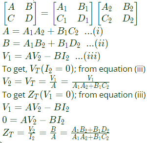
Q4: Two passive two-port networks are connected in cascade as shown in figure. A voltage source is connected at port 1.
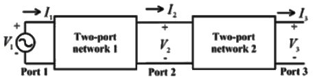
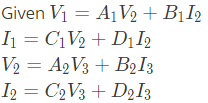 A1, B1, C1, D1, A2, B2, C2 and D2 are the generalized circuit constants. If the Thevenin equivalent circuit at port 3 consists of a voltage source VT and impedance ZT connected in series, then (SET-1 (2017))
(a) 
(b) 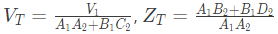
(c) 
(d) 
Ans: (d)
Sol: For two port network, we can write,
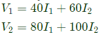
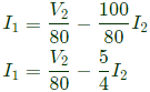
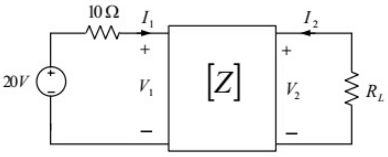
Q5: The z-parameters of the two port network shown in the figure are
z11 = 40Ω, z12 = 60Ω, z21 = 80Ω and z22 = 100Ω.
The average power delivered to RL = 20Ω, in watts, is _______. (SET-2 (2016))
 (a) 18.25
(b) 24.35
(c) 28.45
(d) 35.55
Ans: (d)
Sol: 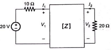
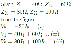 From equation (i) and (iii), we get
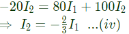 Using equation (ii) and (iv), we get
 From the figure,
 Power dissipated in
Q6: The driving point input impedance seen from the source Vs of the circuit shown below, in Ω, is ______. (SET-2 (2016))
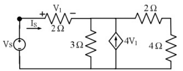 (a) 10
(b) 20
(c) 30
(d) 40
Ans: (b)
Sol: To find impedance seen by Vs

 Applying KCL at node A,
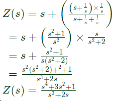
Q7: The driving point impedance Z(s) for the circuit shown below is (SET-3 (2014))
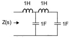 (a)
(a) 
(b) 
(c) 
(d) 
Ans: (a)
Sol: 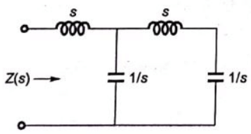 Driving point impedance, Z(s) is ,
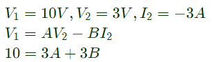
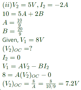
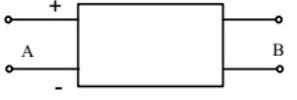
Q8: With 10 V dc connected at port A in the linear nonreciprocal two-port network shown below, the following were observed:
(i) 1 Ω connected at port B draws a current of 3 A
(ii) 2.5 Ω connected at port B draws a current of 2 A
 For the same network, with 6 V dc connected at port A, 1 Ω connected at port B draws 7/3 A. If 8 V dc is connected to port A, the open circuit voltage at port B is (2012)
(a) 6 V
(b) 7 V
(c) 8 V
(d) 9 V
Ans: (b)
Sol: (i)
Q9: With 10 V dc connected at port A in the linear nonreciprocal two-port network shown below, the following were observed:
(i) 1 Ω connected at port B draws a current of 3 A
(ii) 2.5 Ω connected at port B draws a current of 2 A
 With 10 V dc connected at port A, the current drawn by 7 Ω connected at port B is (2012)
(a) 3/7A
(b) 5/7A
(c) 1A
(d) 9/7A
Ans: (c)
Sol: 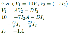 -ve sign is signifies that current is drawn.
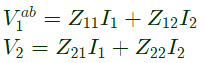
Q10: The two-port network P shown in the figure has ports 1 and 2, denoted by terminals (a, b) and (c, d) respectively. It has an impedance matrix Z with parameters denoted by Zij. A 1 Ω resistor is connected in series with the network at port 1 as shown in the figure. The impedance matrix of the modified two-port network (shown as a dashed box ) is (2010)
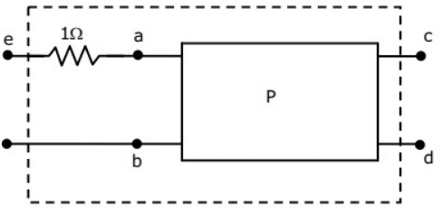 (a)
(a) 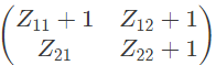
(b) 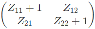
(c) 
(d) 
Ans: (c)
Sol: 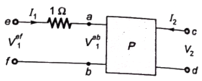
 As, 1Ω resistor is connected in series with the network as port-1.
V2 does not get affected,
 Modified Z-parameter
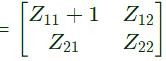
Q11: The parameter type and the matrix representation of the relevant two port parameters that describe the circuit shown are (2006)
 (a) z parameters,
(b) h parameters,
(c) g parameters,
(d) z parameters,
Ans: (c)
Sol: 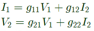
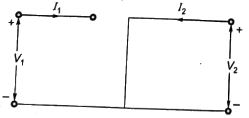 Since port-1 is open circuit, I1 = 0
Port-2 is short-circuit, V2 = 0
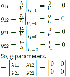
Q12: The parameters of the circuit shown in the figure are
Ri = 1 MΩ, Ro = 10 Ω, A = 106 V/V.
If vi = 1μV, then output voltage, input impedance and output impedance respectively are (2006)
 (a) 1V, ∞, 10Ω
(b) 1 V, 0, 10Ω
(c) 1 V, 0, ∞
(d) 10 V, ∞, 10 Ω
Ans: (a)
Sol: Output voltage V0 = AVi
V0 = 106 × 1 × 10-6 = 1V
To calculate input impedance, Vdc source is connected at input port
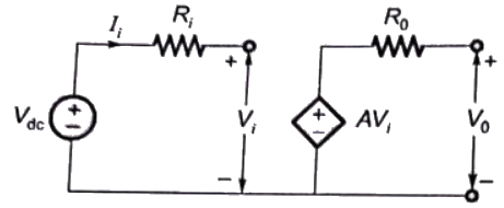 Input impedance
 as loop is not closed, Ii = 0
So, 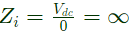
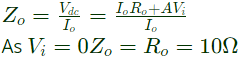
To calculate output impedance, Vdc source is connected at output port.
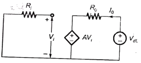 Output impedance,
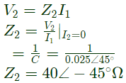
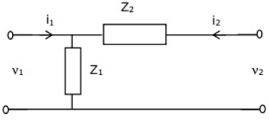
Q13: Two networks are connected in cascade as shown in the figure. With usual notations the equivalent A, B, C and D constants are obtained. Given that, C = 0.025∠45°, the value of Z2 is (2005)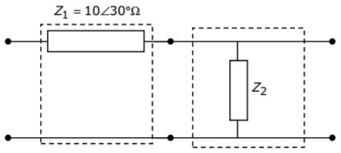 (a) 10∠30°Ω
(b) 40∠-45°Ω
(c) 1 Ω
(d) 0 Ω
Ans: (b)
Sol: 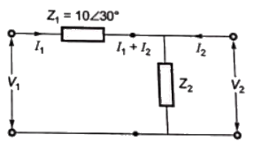
 Putting I2 = 0 in equation (i)
Q14: For the two port network shown in the figure, the Z-matrix is given by (2005)
 (a)
(a) 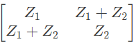
(b) 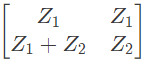
(c) 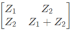
(d) 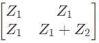
Ans: (d)
Sol: 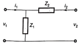
 From above, we can write,
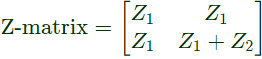
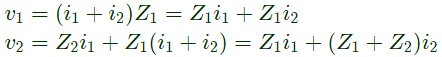
Q15: The Z-matrix of a 2-port network as given by
The element Y22 of the corresponding Y-matrix of the same network is given by (2004)
(a) 1.2
(b) 0.4
(c) -0.4
(d) 1.8
Ans: (d)
Sol: 
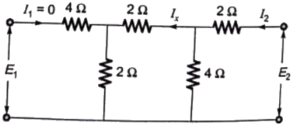
Q16: The h-parameters for a two-port network are defined by 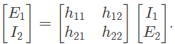 For the two-port network shown in figure, the value of h12 is given by (2003)
 (a) 0.125
(b) 0.167
(c) 0.625
(d) 0.25
Ans: (d)
Sol:  h12 is ratio of E1 to E2 for the input open-circuited condition.
Assuming I1 = 0
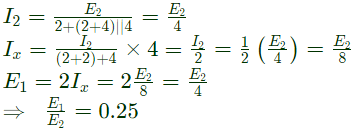
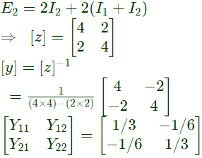
Q17: A two port network, shown in figure is described by the following equations
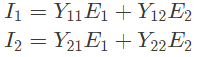
 The admittance parameters Y11, Y12, Y21, Y22 for the network shown are (2002)
(a) 0.5 mho, 1 mho, 2 mho and 1 mho respectively
(b) 1/3 mho, -1/6 mho, -1/6 mho and 1/3 mho respectively
(c) 0.5 mho, 0.5 mho, 1.5 mho and 2 mho respectively
(d) -2/5 mho, -3/7 mho, 3/7 mho and 2/5 mho respectively
Ans: (b)
Sol: Using KVL,
E1 = 2I1 + 2(I1+I2)
Again using KVL,
Q18: A passive 2-port network is in a steady-state. Compared to its input, the steady state output can never offer (2001)
(a) higher voltage
(b) lower impedance
(c) greater power
(d) better regulation
Ans: (c)
Sol: For a passive two port network, output powe can never be grater than input power.


