Q1: A double pulse measurement for an inductively loaded circuit controlled by the IGBT switch is carried out to evaluate the reverse recovery characteristics of the diode. D, represented approximately as a piecewise linear plot of current vs time at diode turn-off. Lpar is a parasitic inductance due to the wiring of the circuit, and is in series with the diode. The point on the plot (indicate your choice by entering 1. 2, 3 or 4) at which the IGBT experiences the highest current stress is ______. (2020)
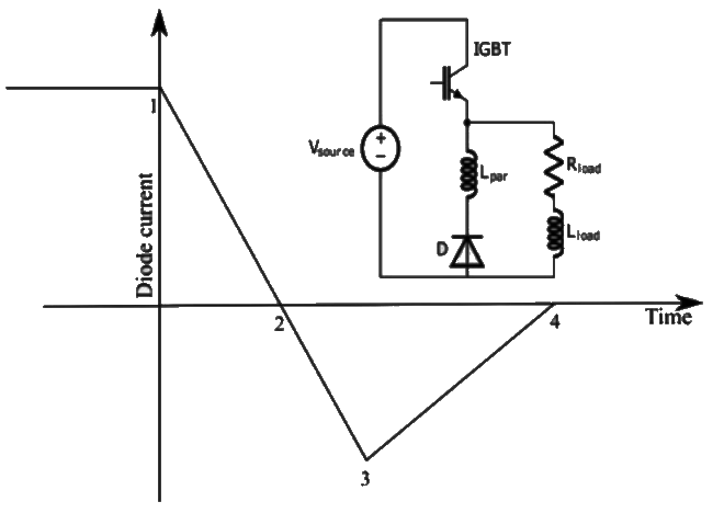 (a) 1
(a) 1
(b) 2
(c) 3
(d) 4
Ans: (c)
Sol: 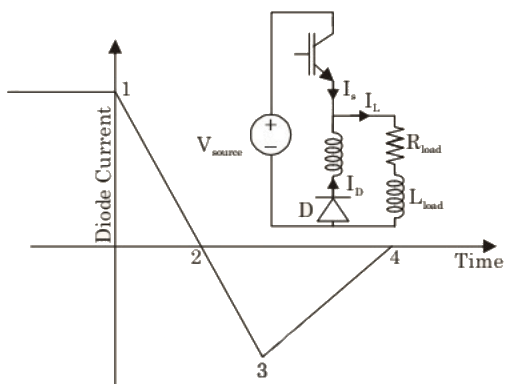 Using KCL, Is = IL − ID
For inductively loaded circuits, load can be assumed to be constant.
∴ Is is maximum when, ID is minimum, i.e. at point 3.
Therefore, IGBT experiences highest current stress at point 3.
Q2: For the circuit shown in the figure below, assume that diodes D1, D2 and D3 are ideal.
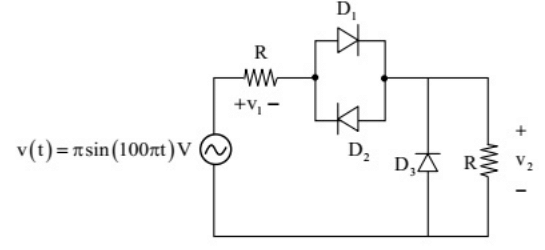 The DC components of voltages v1 and v2, respectively are (SET-1 (2017))
(a) 0 V and 1 V
(b) -0.5 V and 0.5 V
(c) 1 V and 0.5 V
(d) 1 V and 1 V
Ans: (b)
Sol: 

Q3: Consider a HVDC link which uses thyristor based line-commutated converters as shown in the figure. For a power flow of 750 MW from System 1 to System 2, the voltages at the two ends, and the current, are given by: V1 = 500 kV, V2 = 485 kV and V3 = 1.5 kA. If the direction of power flow is to be reversed (that is, from System 2 to System 1) without changing the electrical connections, then which one of the following combinations is feasible? (SET-1 (2015))
 (a) V1 = −500kV, V2 = −485kV and latex]I = 1.5kA[/latex]
(b) V1 = −485kV, V2 = 500kV and latex]I = 1.5kA[/latex]
(c) V1 = 500kV, V2 = −485kV and latex]I = -1.5kA[/latex]
(d) V1 = −500kV, V2 = −485kV and latex]I = -1.5kA[/latex]
Ans: (b)
Sol: To maintain the direction of power flow from system 2 to system 1, the voltage V1 = −485kV and voltage V2 = 500kV and I = 1.5kA.
Since, current cannot flow in reverse direction. Option (B) is correct answer.
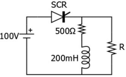
Q4: The SCR in the circuit shown has a latching current of 40 mA. A gate pulse of 50 μs is applied to the SCR. The maximum value of R in Ω to ensure successful firing of the SCR is ______. (SET-2 (2014))
 (a) 4050
(b) 5560
(c) 6060
(d) 8015
Ans: (c)
Sol: Let us assume the SCR is conducting,


Q5: A single-phase SCR based ac regulator is feeding power to a load consisting of 5 Ω resistance and 16 mH inductance. The input supply is 230 V, 50 Hz ac. The maximum firing angle at which the voltage across the device becomes zero all throughout and the rms value of current through SCR, under this operating condition, are (SET-2 (2014))
(a) 30° and 46 A
(b) 30° and 23 A
(c) 45° and 23 A
(d) 45° and 32 A
Ans: (c)
Sol: The maximum firing angle at which the voltage across the device becomes ′ϕ′ = load angle.
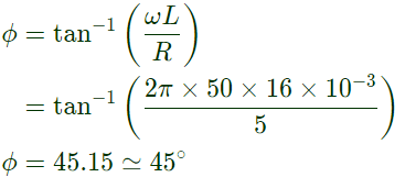 Rms value of current through SCR is


Q6: A solar energy installation utilize a three-phase bridge converter to feed energy into power system through a transformer of 400V/400 V, as shown below.

The energy is collected in a bank of 400 V battery and is connected to converter through a large filter choke of resistance 10Ω.
The kVA rating of the input transformer is (2011)
(a) 53.2 kVA
(b) 46.0 kVA
(c) 22.6 kVA
(d) 7.5 kVA
Ans: (c)
Sol: RMS value of supply current in case of 3 − ϕ bridge converter
 KVA rating of the input transformrer

Q7: A solar energy installation utilize a three-phase bridge converter to feed energy into power system through a transformer of 400V/400 V, as shown below.
 The energy is collected in a bank of 400 V battery and is connected to converter through a large filter choke of resistance10 Ω.
The maximum current through the battery will be (2011)
(a) 14 A
(b) 40 A
(c) 80 A
(d) 94 A
Ans: (b)
Sol:  Average output voltage of the converter
 The converter acts as line commutated inverter and for such mode α > 90° and V0 is negative.THerefore, battery supplies energy to AC system. So, current through battery
 Maximum current flow through battery

Q8: The input voltage given to a converter is  The current drawn by the converter is
 The active power drawn by the converter is (2011)
(a) 181 W
(b) 500 W
(c) 707 W
(d) 887 W
Ans: (b)
Sol: Rms value of input voltag,
 Rms value of current,
 Let input power factor cosϕ
Vrms Irmscosϕ = active power drawn by the coverter
⇒ 100 × 11.358 × cosϕ = 500W
⇒ cosϕ = 0.44
Q9: The input voltage given to a converter is  The current drawn by the converter is
 The input power factor of the converter is (2011)
(a) 0.31
(b) 0.44
(c) 0.5
(d) 0.71
Ans: (c)
Sol: 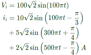 Fundamental component of input voltage
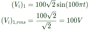 Fundamental component of current
 Phase difference between these two components
 Active power due to fundamental components
P1 = (Vi)1,rms × (ii)1,rms cosϕ = 100 × 10 × 0.5 = 500W
Since 3rd and 5th harmonic are absent in input voltage, there is no active power due to the these components.
Hence, active power drawn by the converter
P0 = Active power due to fundamental components = 500 W
Q10: The power electronic converter shown in the figure has a single-pole double-throw switch. The pole P of the switch is connected alternately to throws A and B. The converter shown is a (2010)
 (a) step down chopper (buck converter)
(b) half-wave rectifier
(c) step-up chopper (boost converter)
(d) full-wave rectifier
Ans: (a)
Sol: When switch is connected to A for time duration T1
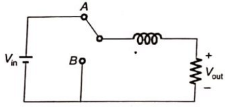 Vout = Vin
When switch is connected to B for time duration T2
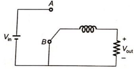 Average output voltage
where, α = duty cycle 
Therefore, the converter shown is a step down chooper.
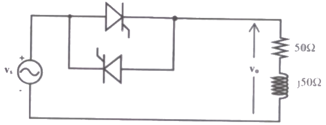
Q11: In the single phase voltage controller circuit shown in the figure, for what range of triggering angle (α), the input voltage (V0) is not controllable ? (2008)
 (a) 0° < α < 45°
(b) 45° < α < 135°
(c) 90° < α < 180°
(d) 135° < α < 180°
Ans: (a)
Sol: Impedance of the load
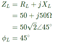 The output voltage (V0) is controllable when α ≥ ϕL, So for 0° < α < 45°, output voltage is not controllable.
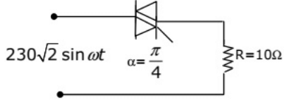
Q12: The triac circuit shown in figure controls the ac output power to the resistive load. The peak power dissipation in the load is (2004)
 (a) 3968 W
(b) 5290 W
(c) 7935 W
(d) 10580 W
Ans: (d)
Sol: 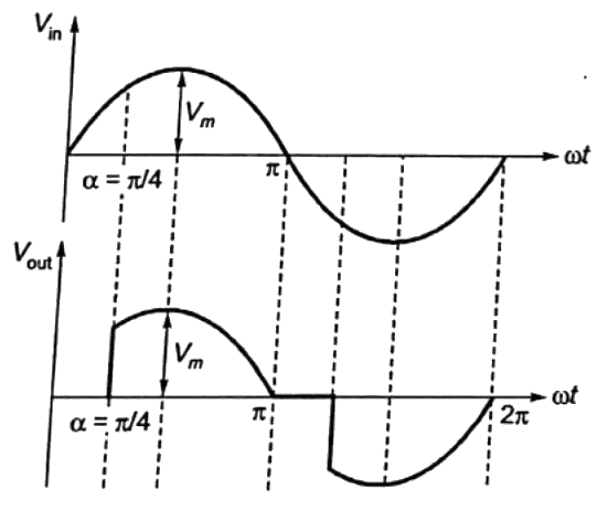 Let Vm is the peak value of input voltage
 As firing angle = α = (π/4), so peak voltage across resistance load is also Vm.
Peak power dissipation in the field

 (a) 1
(a) 1 Using KCL, Is = IL − ID
 The DC components of voltages v1 and v2, respectively are (SET-1 (2017))

 (a) V1 = −500kV, V2 = −485kV and latex]I = 1.5kA[/latex]
 (a) 4050


 Rms value of current through SCR is


 KVA rating of the input transformrer
 The energy is collected in a bank of 400 V battery and is connected to converter through a large filter choke of resistance10 Ω.
 Average output voltage of the converter
 The converter acts as line commutated inverter and for such mode α > 90° and V0 is negative.THerefore, battery supplies energy to AC system. So, current through battery
 Maximum current flow through battery
 The current drawn by the converter is
 The active power drawn by the converter is (2011)
 Rms value of current,
 Let input power factor cosϕ
 The current drawn by the converter is
 The input power factor of the converter is (2011)
 Fundamental component of input voltage
 Fundamental component of current
 Phase difference between these two components
 Active power due to fundamental components
 (a) step down chopper (buck converter)
 Vout = Vin
 Average output voltage

 (a) 0° < α < 45°
 The output voltage (V0) is controllable when α ≥ ϕL, So for 0° < α < 45°, output voltage is not controllable.
 (a) 3968 W
 Let Vm is the peak value of input voltage
 As firing angle = α = (π/4), so peak voltage across resistance load is also Vm.


