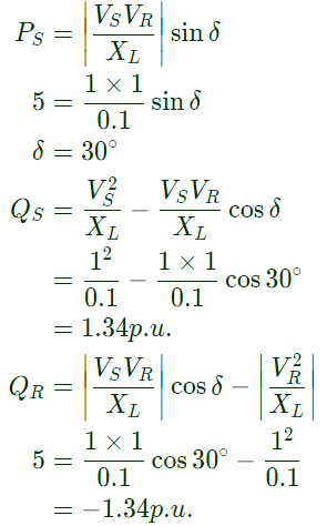
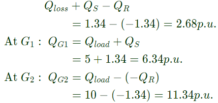
Q1: Consider the two bus power system network with given loads as shown in the figure. All the values shown in the figure are in per unit. The reactive power supplied by generator G1 and G2 are QG1 and QG2 respectively. The per unit values of QG1, QG2, and line reactive power loss (Qloss) respectively are (2018) (a) 5. 00, 12.68, 2.68
(b) 6.34, 10.00, 1.34
(c) 6.34, 11.34, 2.68
(d) 5.00, 11.34, 1.34
Ans: (c)
Sol:  At G2 load demand is 20 pu, G2 supplies only 15 pu. Remaining supplied by G1 through transmission line.
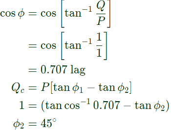
Q2: A load is supplied by a 230 V, 50 Hz source. The active power P and the reactive power Q consumed by the load are such that 1kW ≤ P ≤ 2kW and 1kV AR ≤ Q ≤ kV AR. A capacitor connected across the load for power factor correction generates 1 kVAR reactive power. The worst case power factor after power factor correction is (SET-1 (2017))
(a) 0.447 lag
(b) 0.707 lag
(c) 0.894 lag
(d) 1
Ans: (b)
Sol: 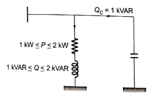 Load p.f.

Q3: The inductance and capacitance of a 400 kV, three-phase, 50 Hz lossless transmission line are 1.6 mH/km/phase and 10 nF/km/phase respectively. The sending end voltage is maintained at 400 kV. To maintain a voltage of 400 kV at the receiving end, when the line is delivering 300 MW load, the shunt compensation required is (SET-2 (2016))
(a) capacitive
(b) inductive
(c) resistive
(d) zero
Ans: (b)
Sol: 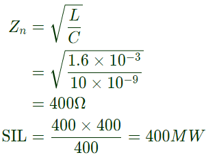 In the second case SIL decreases means Zn increasess.
Zn increases with increase in inductance 'L'.
So, it is inductive.
Load < SIL means, line behaves capacitive to compensate it inductor to be placed.
Q4: The complex power consumed by a constant-voltage load is given by (P1 + jQ1),
 A compensating shunt capacitor is chosen such that ∣Q∣ ≤ 0.25kV AR, where Q is the net reactive power consumed by the capacitor load combination. The reactive power (in kVAR) supplied by the capacitor is ____. (SET-3 (2014))
(a) 0.25
(b) 0.50
(c) 0.75
(d) 0.90
Ans: (c)
Sol: 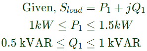 Shunt capacitor will only supply reactive power and the total reactive power consumed by the load and the capacitor together will be less than 0.25 kVAR
i.e. Q ≤ 0.25 kVAR
Therefore, reactive power supplied by the capacitor will be QC = (1 − 0.25) = 0.75 kVAR (lagging)
Q5: Shunt reactors are sometimes used in high voltage transmission systems to (SET-2 (2014))
(a) limit the short circuit current through the line
(b) compensate for the series reactance of the line under heavily loaded condition
(c) limit over-voltages at the load side under lightly loaded condition.
(d) compensate for the voltage drop in the line under heavily loaded condition.
Ans: (c)
Sol: Shunt reactor is basically an inductor having no-core or core is replaced by cement slab to avoid saturation problem. These are widely used to reduce the fault level or the short circuit current through the line.
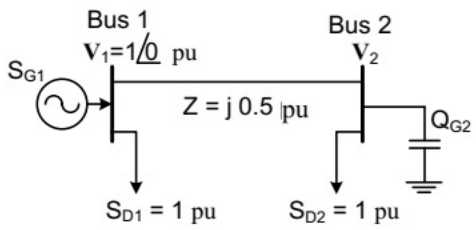
Q6: For the system below, SD1 and SD2 are complex power demands at bus 1 and bus 2 respectively. If ∣V2∣ = 1 pu, the VAR rating of the capacitor (QG2) connected at bus 2 is (2012)
 (a) 0.2 pu
(b) 0.268 pu
(c) 0.312 pu
(d) 0.4 pu
Ans: (b)
Sol: 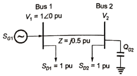 Real power,
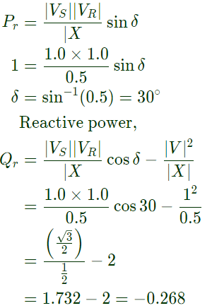

Q7: For enhancing the power transmission in along EHV transmission line, the most preferred method is to connect a (2011)
(a) Series inductive compensator in the line
(b) Shunt inductive compensator at the receiving end
(c) Series capacitive compensator in the line
(d) Shunt capacitive compensator at the sending end
Ans: (c)
Sol: Series capacitance compensation reduces reactance of the line.
Power flow in line ∝ (1/(reactance of the line))
As reactance of line decreases, power flow in the line Ca increases.
Q8: Match the items in List-I (To) with the items in the List-II (Use) and select the correct answer using the codes given below the lists. (2009)
 (a) a - 2, b - 3, c - 4, d - 1
(b) a - 2 , b - 4, c - 3, d - 1
(c) a - 4 , b - 3, c - 1, d - 2
(d) a - 4 , b - 1, c - 3, d - 2
Ans: (b)
Sol: Shunt capacitor are used to provide part of the reactive VAR's required by the load to keep the voltage within desirable limits and to improve factor.
Series reactor reduce current ripple.
Shunt reactors are used across capacitive loads or ligjtly loaded lines to absorb some of the leading VARs to control the voltage across the load to within certain desirable limit.
Series capacitor compensation reduces the series impedance of the line. Power flow in line ∝ 1/XL, power flow in line increases, as XL decreases.
Q9: A loss less transmission line having Surge Impedance Loading (SIL) of 2280 MW is provided with a uniformly distributed series capacitive compensation of 30%. Then, SIL of the compensated transmission line will be (2008)
(a) 1835 MW
(b) 2280 MW
(c) 2725 MW
(d) 3257 MW
Ans: (c)
Sol: Surge impedance loading= SIL = 2280 MW
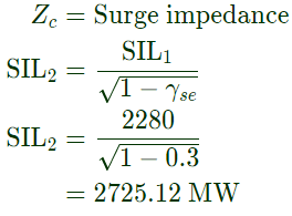
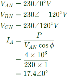
Q10: A 230 V (Phase), 50 Hz, three-phase, 4-wire, system has a phase sequence ABC. A unity power-factor load of 4 kW is connected between phase A and neutral N. It is desired to achieve zero neutral current through the use of a pure inductor and a pure capacitor in the other two phases. The value of inductor and capacitor is (2007)
(a) 72.95 mH in phase C and 139.02 μF in Phase B
(b) 72.95 mH in Phase B and 139.02 μF in Phase C
(c) 42.12 mH in Phase C and 240.79 μF in Phase B
(d) 42.12 mH in Phase B and 240.79 μF in Phase C
Ans: (b)
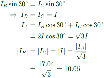
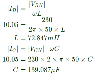
Sol: 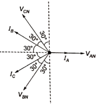 Taking VAN as the reference
 If an pure inductor is present in phase B, then IB lags VBN by 90°.
If a pure capacitor is present in phase C, then IC leads VCN by 90°.
If current through neutral is to be zero.
Q11: The figure below shows a three phase self-commutated voltage source converter connected to a power system. The converter's dc bus capacitor is marked as C in the figure. The circuit in initially operating in steady state with δ = 0 and the capacitor dc voltage is equal to Vdc0. You may neglect all losses and harmonics. What action should be taken to increase the capacitor dc voltage slowly to a new steady state value. (2007) (a) Make δ positive and maintain it at a positive value
(b) Make δ positive and return it to its original value
(c) Make δ negative and maintain it at a negative value
(d) Make δ negative and return it to its original value
Ans: (d)
Sol: To increase the capacitor dc voltage, energy has to be supplied by the generator to capacitor through converter.
Power flow from higher angle to lower angle. As angle of induced emf of generator is 0, so δ should be made negative to make the power flow in required direction.
Q12: A 400 V, 50 Hz, three phase balanced source supplies power to a star connected load whose rating is 12√3 kVA, 0.8 pf (lag). The rating (in kVAR) of the delta connected (capacitive) reactive power bank necessary to bring the pf to unity is (2006)
(a) 28.78
(b) 21.6
(c) 16.6
(d) 12.47
Ans: (d)
Sol: Rating of the load 12√3 at 0.8 pf lag
Active power demand of the load
 Reactive power demand of the laod
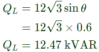 For unity pf, the total reactive power is zero. Assuming kVAR rating of capacitor bank = QC
 So, capacitor banks supplies 12.47 KVAR reactive power to the load.
Q13: At an industrial sub-station with a 4 MW load, a capacitor of 2 MVAR is installed to maintain the load power factor at 0.97 lagging. If the capacitor goes out of service, the load power factor becomes (2005)
(a) 0.85 lag
(b) 1 lag
(c) 0.80 lag
(d) 0.90 lag
Ans: (c)
Sol: 
Q14: A 3-phase 11 kV generator feeds power to a constant power unity power factor load of 100 MW through a 3-phase transmission line. The line-to line voltage at the terminals of the machine is maintained constant at 11 kV. The per unit positive sequence impedance of the line based on 100 MVA and 11 kV is j0.2. The line to line voltage at the load terminals is measured to be less than 11 kV. The total reactive power to be injected at the terminals of the load to increase the line-to-line voltage at the load terminals to 11 kV is (2003)
(a) 100 MVAR
(b) 10.1 MVAR
(c) -100 MVAR
(d) -10.1 MVAR
Ans: (b)
Sol: ∣Vs∣ = ∣VR∣ = 11kV
p.u. impedance of the line = j0.2 p.u.
Impedance of the line = p.u. impedance x Base impedance
 Active power at receiving end = PR = 100MW
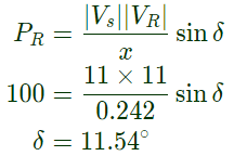 Reactive power at receiving end
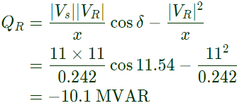 Since poer factor = 1
Load reactive power should be zero
Therefore, reactive power to be injected at terminals −QR = −(−10.1) = 10.1 MVAR
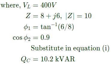
Q15: A balanced delta connected load of (8 + j6) Ω per phase is connected to a 400 V, 50 Hz, 3-phase supply lines. If the input power factor is to be improved to 0.9 by connecting a bank of star connected capacitor the required kVAR of the of the bank is (2003)
(a) 42.7
(b) 10.2
(c) 28.8
(d) 38.4
Ans: (b)
Sol: 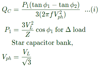
Q16: Consider the model shown in figure of a transmission line with a series capacitor at its mid-point. The maximum voltage on the line is at the location (2001)
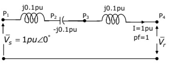 (a) P1
(b) P2
(c) P3
(d) P4
Ans: (c)
Sol: 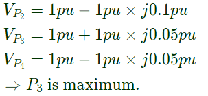
Q17: A lossless radial transmission line with surge impedance loading (2001)
(a) takes negative VAR at sending end and zero VAR at receiving end
(b) takes positive VAR at sending end and zero VAR at receiving end
(c) has flat voltage profile and unity power factor at all points along it
(d) has sending end voltage higher than receiving end voltage and unity power factor at sending end
Ans: (c)
 (a) 5. 00, 12.68, 2.68
 At G2 load demand is 20 pu, G2 supplies only 15 pu. Remaining supplied by G1 through transmission line.

 Load p.f.

 In the second case SIL decreases means Zn increasess.
 A compensating shunt capacitor is chosen such that ∣Q∣ ≤ 0.25kV AR, where Q is the net reactive power consumed by the capacitor load combination. The reactive power (in kVAR) supplied by the capacitor is ____. (SET-3 (2014))
 Shunt capacitor will only supply reactive power and the total reactive power consumed by the load and the capacitor together will be less than 0.25 kVAR
 (a) 0.2 pu
 Real power,

 (a) a - 2, b - 3, c - 4, d - 1
 Taking VAN as the reference
 If an pure inductor is present in phase B, then IB lags VBN by 90°.

 (a) Make δ positive and maintain it at a positive value
 Reactive power demand of the laod
 For unity pf, the total reactive power is zero. Assuming kVAR rating of capacitor bank = QC
 So, capacitor banks supplies 12.47 KVAR reactive power to the load.
 Active power at receiving end = PR = 100MW
 Reactive power at receiving end
 Since poer factor = 1

 (a) P1


