Electrical Engineering (EE) Exam  >  Electrical Engineering (EE) Notes  >  Power Systems  >  Previous Year Questions- Distribution Systems, Cables and Insulators

Previous Year Questions- Distribution Systems, Cables and Insulators | Power Systems - Electrical Engineering (EE) PDF Download

Q1: If only 5% of the supplied power to a cable reaches the output terminal, the power loss in the cable, in decibels, is _________. (round off to nearest integer)       (2022)
(a) 8
(b) 13
(c) 17
(d) 15
Ans:
(b)
Sol: We have, the power loss (in decibel) in the cable is given power loss = 95%
Power output as a % of power is 5%
PL = 10 log (95/5) = 12.78.

Q2: Two single-core power cables have total conductor resistances of 0.7Ω and 0.5Ω, respectively, and their insulation resistances (between core and sheath) are 600MΩ and 900MΩ, respectively. When the two cables are joined in series, the ratio of insulation resistance to conductor resistance is ___________ × 106.       (2021)
(a) 300
(b) 100
(c) 150
(d) 600
Ans:
(a)
Sol: Previous Year Questions- Distribution Systems, Cables and Insulators | Power Systems - Electrical Engineering (EE)
Q3: A three-phase cable is supplying 800 kW and 600 kVAr to an inductive load. It is intended to supply an additional resistive load of 100 kW through the same cable without increasing the heat dissipation in the cable, by providing a three-phase bank of capacitors connected in star across the load. Given the line voltage is 3.3 kV, 50 Hz, the capacitance per phase of the bank, expressed in microfarads, is ________.      (SET-1 (2016))
(a) 500.42
(b) 19.25
(c) 47.96
(d) 98.32
Ans: 
(c)
Sol: Previous Year Questions- Distribution Systems, Cables and Insulators | Power Systems - Electrical Engineering (EE)Without excessive heat dissipation means current should be constant (i.e.) KVA erating must be constatn.
In second case active power,
P = 800 + 100 = 900 KW
Reactive power in second case,
Previous Year Questions- Distribution Systems, Cables and Insulators | Power Systems - Electrical Engineering (EE)Reactive power supplied by the three phase bank = 600 - 435.889 = 164.44 KVAR
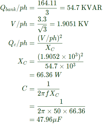
Previous Year Questions- Distribution Systems, Cables and Insulators | Power Systems - Electrical Engineering (EE)
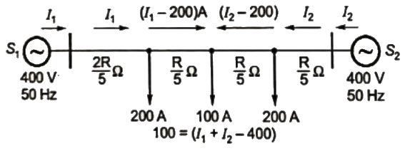
Q4: A distribution feeder of 1 km length having resistance, but negligible reactance, is fed from both the ends by 400 V, 50 Hz balanced sources. Both voltage sources S1 and S2 are in phase. The feeder supplies concentrated loads of unity power factor as shown in the figure.
Previous Year Questions- Distribution Systems, Cables and Insulators | Power Systems - Electrical Engineering (EE)The contributions of S1 and S2 in 100 A current supplied at location P respectively, are       (SET-1 (2014))
(a) 75 A and 25 A
(b) 50 A and 50 A
(c) 25 A and 75 A
(d) 0 A and 100 A
Ans:
(d)
Sol: Let the resistance of whole length of feeder be RΩ, length of feeder =1000m.
∴ Resistance per unit length Previous Year Questions- Distribution Systems, Cables and Insulators | Power Systems - Electrical Engineering (EE)
∴ Resistance of 400 m length Previous Year Questions- Distribution Systems, Cables and Insulators | Power Systems - Electrical Engineering (EE)
∴ Resistance of 200 m length = (R/5) Ω
Let the current supplied by the sources be I1 and I2.
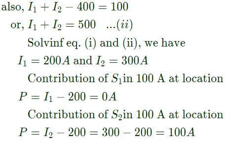
Previous Year Questions- Distribution Systems, Cables and Insulators | Power Systems - Electrical Engineering (EE)Applying KVL from source S1 and S2, we have:  
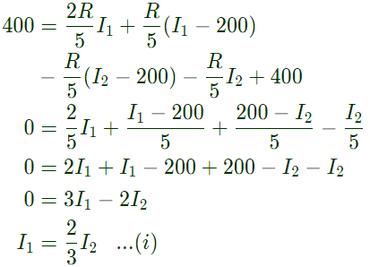
Previous Year Questions- Distribution Systems, Cables and Insulators | Power Systems - Electrical Engineering (EE)Previous Year Questions- Distribution Systems, Cables and Insulators | Power Systems - Electrical Engineering (EE)Therefore, S2 alone supplies the total load at location P.
Q5: The undesirable property of an electrical insulating material is      (SET-1 (2014))
(a) high dielectric strength
(b) high relative permittivity
(c) high thermal conductivity
(d) high insulation resistivity
Ans: 
(b)

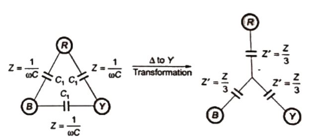
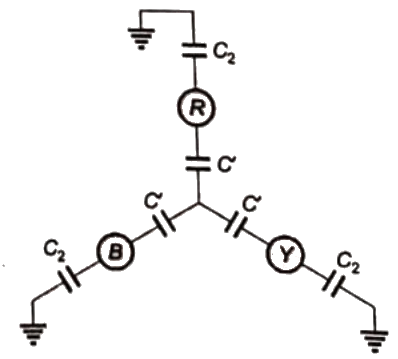
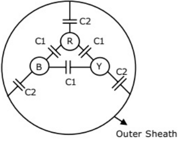
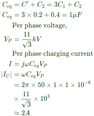
Q6: Consider a three-core, three-phase, 50 Hz, 11 kV cable whose conductors are denoted as R,Y and B in the figure. The inter-phase capacitance(C1) between each pair of conductors is 0.2 μF and the capacitance between each line conductor and the sheath is 0.4 μF . The per-phase charging current is      (2010)
Previous Year Questions- Distribution Systems, Cables and Insulators | Power Systems - Electrical Engineering (EE)(a) 2.0 A
(b) 2.4 A
(c) 2.7 A
(d) 3.5 A
Ans: 
(a)
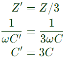
Sol: Previous Year Questions- Distribution Systems, Cables and Insulators | Power Systems - Electrical Engineering (EE)Previous Year Questions- Distribution Systems, Cables and Insulators | Power Systems - Electrical Engineering (EE)Previous Year Questions- Distribution Systems, Cables and Insulators | Power Systems - Electrical Engineering (EE)Equivalent capacitance (Ceq) between a phase and ground
Previous Year Questions- Distribution Systems, Cables and Insulators | Power Systems - Electrical Engineering (EE)
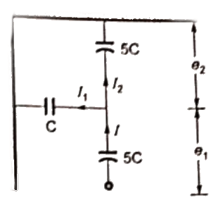
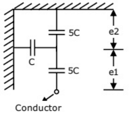
Q7: Consider a three-phase, 50 Hz, 11 kV distribution system. Each of the conductors is suspended by an insulator string having two identical porcelain insulators. The self capacitance of the insulator is 5 times the shunt capacitance between the link and the ground, as shown in the figures. The voltages across the two insulators are       (2010)Previous Year Questions- Distribution Systems, Cables and Insulators | Power Systems - Electrical Engineering (EE)(a) e1=3.74kV,e2=2.61kVe1 = 3.74kV, e2 = 2.61kV  
(b) e1=3.46kV,e2=2.89kVe= 3.46kV, e2 = 2.89kV
(c) e1=6.0kV,e2=4.23kVe1 = 6.0kV, e2 = 4.23kV
(d) e1=5.5kV,e2=5.5kVe= 5.5kV, e2 = 5.5kV
Ans:
(b)
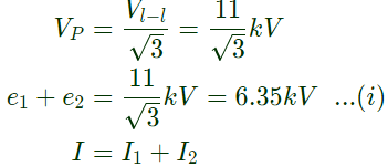
Sol: Previous Year Questions- Distribution Systems, Cables and Insulators | Power Systems - Electrical Engineering (EE)Line to line voltage = Vl-l = 11 kV
VP = Phase to ground voltage
Previous Year Questions- Distribution Systems, Cables and Insulators | Power Systems - Electrical Engineering (EE)Previous Year Questions- Distribution Systems, Cables and Insulators | Power Systems - Electrical Engineering (EE)Previous Year Questions- Distribution Systems, Cables and Insulators | Power Systems - Electrical Engineering (EE)
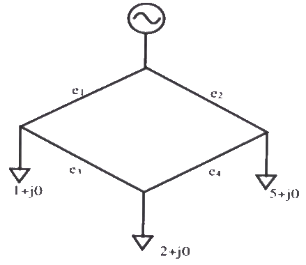
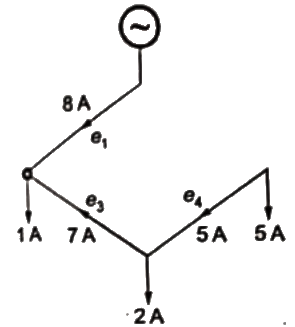
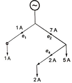
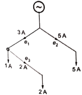
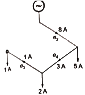
Q8: Single line diagram of a 4-bus single source distribution system is shown below. Branches e1, e2, e3 and e4 have equal impedances. The load current values indicated in the figure are in per unit.
Previous Year Questions- Distribution Systems, Cables and Insulators | Power Systems - Electrical Engineering (EE)Distribution company's policy requires radial system operation with minimum loss. This can be achieved by opening of the branch      (2008)
(a) e1
(b) e2
(c) e3
(d) e4
Ans: 
(d)
Sol: Assuming impedance of each branch R
(i) if eis opened
Previous Year Questions- Distribution Systems, Cables and Insulators | Power Systems - Electrical Engineering (EE)Total losse = 82R + 32R + 12R = 74R
(ii) if e2 is opened
Previous Year Questions- Distribution Systems, Cables and Insulators | Power Systems - Electrical Engineering (EE)Total losses = 82R + 72R + 52R = 138R
(i) if e3 is opened  
Previous Year Questions- Distribution Systems, Cables and Insulators | Power Systems - Electrical Engineering (EE)Total losses =12R + 72R + 22R = 54R
(i) if e4 is opened
Previous Year Questions- Distribution Systems, Cables and Insulators | Power Systems - Electrical Engineering (EE)Total losses = 52R + 32R + 12R = 38R
Operation with minimum loss can be achieved by opening line e4.  

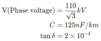
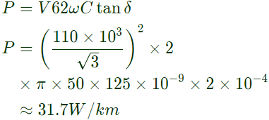
Q9: A 110 kV, single core coaxial, XLPE insulated power cable delivering power at 50 Hz, has a capacitance of 125 nF/km. If the dielectric loss tangent of XLPE is 2 × 10⁻⁴, then dielectric power loss in this cable in W/km is       (2004)
(a) 5
(b) 31.7
(c) 37.8
(d) 189
Ans:
(b)
Sol: Previous Year Questions- Distribution Systems, Cables and Insulators | Power Systems - Electrical Engineering (EE)Previous Year Questions- Distribution Systems, Cables and Insulators | Power Systems - Electrical Engineering (EE)Dielectric power loss in cable
Previous Year Questions- Distribution Systems, Cables and Insulators | Power Systems - Electrical Engineering (EE)
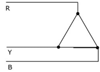
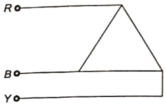
Q10: The phase sequences of the 3-phase system shown in figure is        (2004)
Previous Year Questions- Distribution Systems, Cables and Insulators | Power Systems - Electrical Engineering (EE)(a) RYB
(b) RBY
(c) BRY
(d) YBR
Ans:
(b)
Sol: The phase sequence of the given figure is RBY.
RYB, BRY, and YBR represent the same phase sequence of the figure (given below).
Previous Year Questions- Distribution Systems, Cables and Insulators | Power Systems - Electrical Engineering (EE)
Q11: The rated voltage of a 3-phase power system is given as      (2004)
(a) rms phase voltage
(b) peak phase voltage
(c) rms line to line voltage
(d) peak line to line voltage
Ans
(c)
Sol: NOTE:
Generator are specified in 3 − ϕ MVA, line to line voltage and per-phase reactance (equivalent star).
Tranformers are specified in 3 − ϕ MVA, line to line transformation ratio and per phase (equivalent star) impedance on one side.
Load are specified in 3 − ϕ MVA, line to line voltage and power factor.

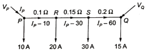
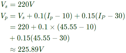
Q12: A dc distribution system is shown in figure with load current as marked. The two ends of the feeder are fed by voltage sources such that V− VQ = 3V. The value of the voltage VP for a minimum voltage of 220 V at any point along the feeder is     (2003)
Previous Year Questions- Distribution Systems, Cables and Insulators | Power Systems - Electrical Engineering (EE)(a) 225.89 V
(b) 222.89 V
(c) 220.0 V
(d) 228.58 V
Ans:
(a)
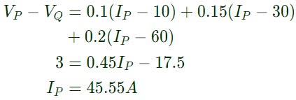
Sol: Let current injected at point P = IP 
Previous Year Questions- Distribution Systems, Cables and Insulators | Power Systems - Electrical Engineering (EE)Previous Year Questions- Distribution Systems, Cables and Insulators | Power Systems - Electrical Engineering (EE)direction of current will be in opposite in section SQ, so, points will have minimum voltage,
Previous Year Questions- Distribution Systems, Cables and Insulators | Power Systems - Electrical Engineering (EE)

The document Previous Year Questions- Distribution Systems, Cables and Insulators | Power Systems - Electrical Engineering (EE) is a part of the Electrical Engineering (EE) Course Power Systems.
All you need of Electrical Engineering (EE) at this link: Electrical Engineering (EE)
21 videos|67 docs|45 tests

Top Courses for Electrical Engineering (EE)

FAQs on Previous Year Questions- Distribution Systems, Cables and Insulators - Power Systems - Electrical Engineering (EE)

1. What are the main components of a distribution system in electrical engineering?
Ans.The main components of a distribution system include substations, transformers, distribution lines (overhead and underground), and service connections. Substations step down high voltage from transmission lines to a lower voltage suitable for distribution. Transformers further adjust the voltage levels, while distribution lines carry electrical power to consumers. Service connections link the distribution system to individual customers.
2. How do different types of cables impact electrical distribution?
Ans.Different types of cables, such as overhead conductors, underground cables, and fiber optic cables, impact electrical distribution based on their material, insulation type, and construction. For example, overhead conductors are typically made of aluminum or copper and are designed for high current capacity, while underground cables need robust insulation to withstand moisture and soil conditions. The choice of cable affects efficiency, cost, and reliability of the distribution system.
3. What is the role of insulators in electrical distribution systems?
Ans.Insulators play a crucial role in electrical distribution systems by preventing unwanted flow of current to the ground and ensuring that electrical conductors remain isolated. They are used to support and separate electrical conductors from towers or poles, thereby maintaining safety and preventing short circuits. Materials such as porcelain, glass, and composite materials are commonly used for insulators due to their high dielectric strength.
4. What factors should be considered when selecting cables for a distribution system?
Ans.When selecting cables for a distribution system, factors such as voltage rating, current carrying capacity, environmental conditions (temperature, moisture), mechanical strength, insulation type, and installation method must be considered. Additionally, economic factors, such as cost and lifespan of the cable, as well as regulatory standards, should also influence the selection process to ensure safety and efficiency.
5. What are the common types of distribution systems used in electrical engineering?
Ans.Common types of distribution systems include radial, looped, and network systems. A radial distribution system has a single power source and branches out to consumers, while a looped distribution system features a closed loop for redundancy and reliability. Network systems provide multiple pathways for electricity to reach consumers, enhancing reliability but at a higher complexity and cost. Each system has its own advantages and is chosen based on the specific requirements of the area being served.
21 videos|67 docs|45 tests
Download as PDF
Explore Courses for Electrical Engineering (EE) exam

Top Courses for Electrical Engineering (EE)

Signup for Free!
Signup to see your scores go up within 7 days! Learn & Practice with 1000+ FREE Notes, Videos & Tests.
10M+ students study on EduRev
Related Searches

Previous Year Questions with Solutions

,

Cables and Insulators | Power Systems - Electrical Engineering (EE)

,

Cables and Insulators | Power Systems - Electrical Engineering (EE)

,

Cables and Insulators | Power Systems - Electrical Engineering (EE)

,

Objective type Questions

,

ppt

,

practice quizzes

,

Sample Paper

,

Previous Year Questions- Distribution Systems

,

Previous Year Questions- Distribution Systems

,

Free

,

Summary

,

Important questions

,

Previous Year Questions- Distribution Systems

,

Extra Questions

,

pdf

,

Semester Notes

,

Viva Questions

,

MCQs

,

past year papers

,

shortcuts and tricks

,

mock tests for examination

,

video lectures

,

Exam

,

study material

;