Q1: The single line diagram of a lossless system is shown in the figure. The system is operating in steady-state at a stable equilibrium point with the power output of the generator being Pmaxsinδ. where δ is the load angle and the mechanical power input is 0.5Pmax. A fault occurs on line 2 such that the power output of the generator is less than 0.5. Pmax during the fault. After the fault is cleared by opening line 2. The power output of the generator is {Pmax/√2}sinδ. If the critical fault clearing angle is π/2 radians, the accelerating area on the power angle carve is ______ times Pmax (rounded off to 2 decimal places) (2024)
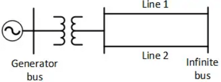 (a) 0.25
(b) 0.11
(c) 0.36
(d) 0.42
Ans: (b)
Sol: 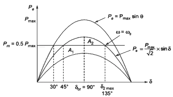 A1 = A2

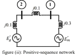
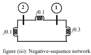
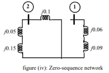
Q2: The two-bus power system shown in figure (i) has one alternator supplying a synchronous motor load through a Y − Δ transformer. The positive, negative and zero-sequence diagrams of the system are shown in figures (ii), (iii) and (iv), respectively. All reactances in the sequence diagrams are in p.u. For a bolted line-to-line fault (fault impedance = zero) between phases 'b' and 'c' at bus 1, neglecting all pre-fault currents, the magnitude of the fault current (from phase 'b' to 'c') in p.u. is _____ (Round off to 2 decimal places). (2023)
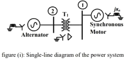
 (a) 7.22
(b) 5.47
(c) 6.98
(d) 9.82
Ans: (a)
Sol: From positive sequence network :
 From negative sequence network :
 For L − L fault,
Fault current, 
Q3: The valid positive, negative and zero sequence impedances (in p.u.), respectively, for a 220 kV, fully transposed three-phase transmission line, from the given choices are (2022)
(a) 1.1, 0.15 and 0.08
(b) 0.15, 0.15 and 0.35
(c) 0.2, 0.2 and 0.2
(d) 0.1, 0.3 and 0.1
Ans: (b)
Sol: We have,
X0 > X1 = X2
(for 3 − ϕ transposed transmission line)
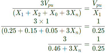
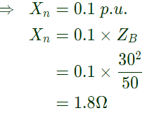
Q4: A 30 kV, 50 Hz, 50 MVA generator has the positive, negative, and zero sequence reactancesof 0.25 pu, 0.15 pu, and 0.05 pu, respectively. The neutral of the generator is grounded with a reactance so that the fault current for a bolted LG fault and that of a bolted three-phase fault at the generator terminal are equal. The value of grounding reactance in ohms (round off to one decimal place) is ______ (2019)
(a) 2.2
(b) 1.8
(c) 3.6
(d) 4.2
Ans: (b)
Sol: 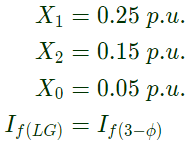
Q5: Five alternators each rated 5 MVA, 13.2 kV with 25% of reactance on its own base are connected in parallel to a busbar. The short-circuit level in MVA at the busbar is_________ (2019)
(a) 50
(b) 75
(c) 100
(d) 150
Ans: (c)
Sol: Net reactance of parallel connection,
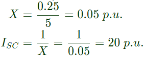 SC MVA = 20 x 5 = 100 MVA
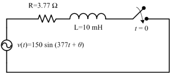
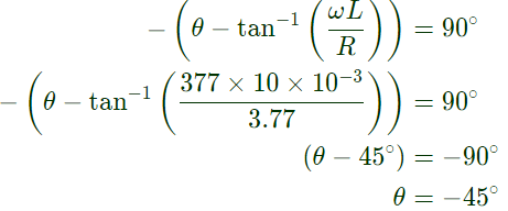
Q6: In the circuit shown below, the switch is closed at t = 0. The value of θ in degrees which will give the maximum value of DC offset of the current at the time of switching is (2019)
 (a) 60
(b) -45
(c) 90
(d) -30
Ans: (b)
Sol: If the switch is closed at t = 0 in series R-L circuit. Then the circuit current i(t) expression is
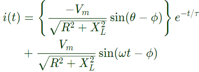 The first term of expression indicates DC offset current.
For maximum value of DC offset current, the angle should be 90°
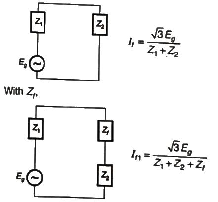
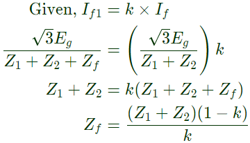
Q7: The positive, negative and zero sequence impedances of a three phase generator are Z1, Z2 and Z0 respectively. For a line-to-line fault with fault impedance Zf ,the fault current is If1 = kIf , where If is the fault current with zero fault impedance. The relation between Zf and k is (2018)
(a) 
(b) 
(c) 
(d) 
Ans: (a)
Sol: For LL fault:
Without Zf
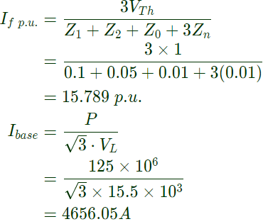
Q8: The positive, negative and zero sequence impedances of a 125 MVA, three-phase, 15.5 kV, star-grounded, 50 Hz generator are j0.1 pu, j0.05 pu and j0.01 pu respectively on the machine rating base. The machine is unloaded and working at the rated terminal voltage. If the grounding impedance of the generator is j0.01 pu, then the magnitude of fault current for a b-phase to ground fault (in kA) is __________ (up to 2 decimal places). (2018)
(a) 35.82
(b) 73.52
(c) 87.23
(d) 97.66
Ans: (b)
Sol: For LG fault,

Q9: The series impedance matrix of a short three-phase transmission line in phase coordinates is
 If the positive sequence impedance is (1 + j10)Ω, and the zero sequence is (4 + j31)Ω, then the imaginary part of Zm (in Ω) is ______(up to 2 decimal places). (2018)
(a) 3
(b) 5
(c) 7
(d) 9
Ans: (c)
Sol:  we know.
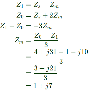 The imaginary part of Zm is 7.00.
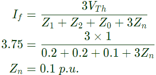
Q10: The positive, negative and zero sequence reactances of a wye-connected synchronous generator are 0.2 pu, 0.2 pu, and 0.1 pu, respectively. The generator is on open circuit with a terminal voltage of 1 pu. The minimum value of the inductive reactance, in pu, required to be connected between neutral and ground so that the fault current does not exceed 3.75 pu if a single line to ground fault occurs at the terminals is _______ (assume fault impedance to be zero). (SET-1 (2017))
(a) 0.033
(b) 0.05
(c) 0.1
(d) 0.2
Ans: (c)
Sol: 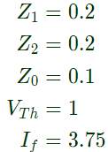
For LG fault,
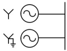
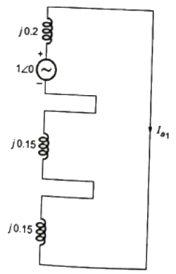
Q11: Two identical unloaded generators are connected in parallel as shown in the figure. Both the generators are having positive, negative and zero sequence impedances of j0.4 p.u., j0.3 p.u. and j0.15 p.u., respectively. If the pre-fault voltage is 1 p.u., for a line-to-ground (L-G) fault at the terminals of the generators, the fault current, in p.u., is ___________. (SET-2 (2016))
 (a) 4.5
(b) 8.9
(c) 6.0
(d) 9.6
Ans: (c)
Sol: 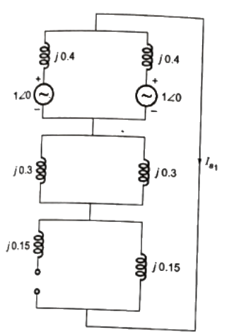

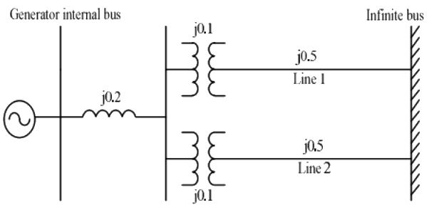
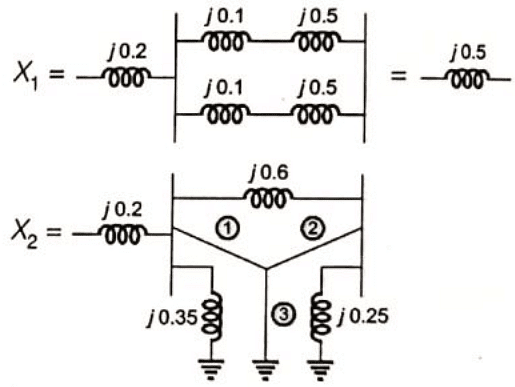
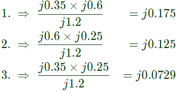
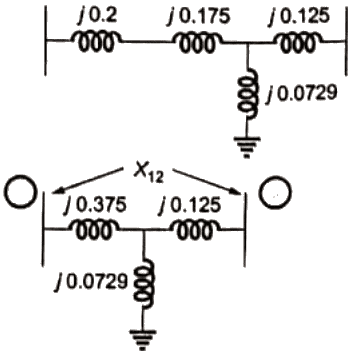
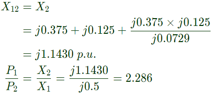
Q12: The single line diagram of a balanced power system is shown in the figure. The voltage magnitude at the generator internal bus is constant and 1.0 p.u. The p.u. reactances of different components in the system are also shown in the figure. The infinite bus voltage magnitude is 1.0 p.u. A three phase fault occurs at the middle of line 2.
The ratio of the maximum real power that can be transferred during the pre-fault condition to the maximum real power that can be transferred under the faulted condition is _________. (SET-2 (2016))
 (a) 2.28
(b) 1.25
(c) 3.65
(d) 1.82
Ans: (a)
Sol: 
Q13: A 50 MVA, 10 kV, 50 Hz, star-connected, unloaded three-phase alternator has a synchronous reactance of 1 p.u. and a sub-transient reactance of 0.2 p.u. If a 3-phase short circuit occurs close to the generator terminals, the ratio of initial and final values of the sinusoidal component of the short circuit current is ________. (SET-2 (2016))
(a) 3
(b) 4
(c) 5
(d) 6
Ans: (c)
Sol: 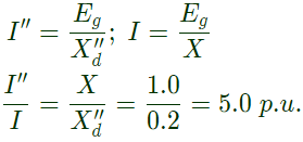
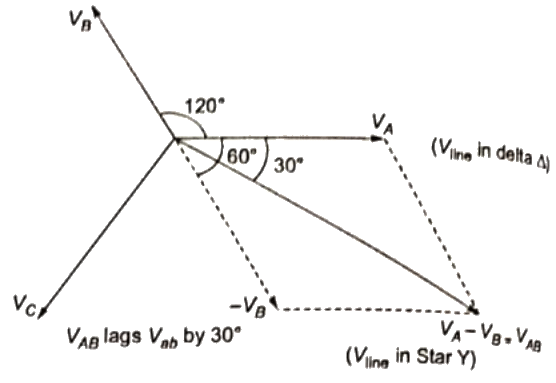
Q14: If the star side of the star-delta transformer shown in the figure is excited by a negative sequence voltage, then (SET-1(2016))
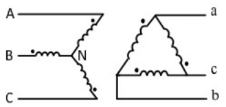 (a) VAB leads Vab by 60°
(b) VAB lags Vab by 60°
(c) VAB leads Vab by 30°
(d) VAB lags Vab by 30°
Ans: (d)
Sol: According to negative sequence phasors.
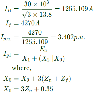
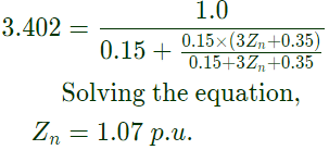
Q15: A 30 MVA, 3-phase, 50 Hz, 13.8 kV, star-connected synchronous generator has positive, negative and zero sequence reactances, 15%, 15% and 5% respectively. A reactance (Xn) is connected between the neutral of the generator and ground. A double line to ground fault takes place involving phases 'b' and 'c', with a fault impedance of j0.1 p.u. The value of Xn (in p.u.) that will limit the positive sequence generator current to 4270 A is _________. (SET-1 (2016))
(a) 1.07
(b) 0.55
(c) 1.85
(d) 2.10
Ans: (a)
Sol: Base current,
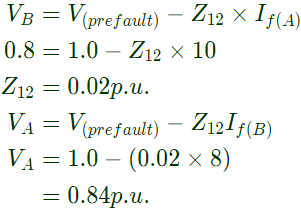
Q16: The magnitude of three-phase fault currents at buses A and B of a power system are 10 pu and 8 pu, respectively. Neglect all resistances in the system and consider the pre-fault system to be unloaded. The pre-fault voltage at all buses in the system is 1.0 pu. The voltage magnitude at bus B during a three-phase fault at bus A is 0.8 pu. The voltage magnitude at bus A during a three-phase fault at bus B, in pu, is ________. (SET-1(2016))
(a) 0.84
(b) 0.44
(c) 0.98
(d) 1.5
Ans: (a)
Sol: Voltage at bus B after 3-phase fault at A = 0.8 p.u.
Q17: A sustained three-phase fault occurs in the power system shown in the figure. The current and voltage phasors during the fault (on a common reference), after the natural transients have died down, are also shown. Where is the fault located? (SET-1(2015)
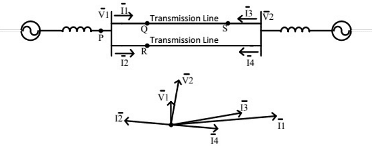 (a) Location P
(b) Location Q
(c) Location R
(d) Location S
Ans: (b)
Sol: From the phasor I2 and I4 are having 180° phase shift. ∣I1∣ is higher than all other. Hence fault occurred at point Q.
Q18: For a fully transposed transmission line (SET-3 (2014))
(a) positive, negative and zero sequence impedances are equal
(b) positive and negative sequence impedances are equal
(c) zero and positive sequence impedances are equal
(d) negative and zero sequence impedances are equal
Ans: (b)
Sol: For a transmission line (static device),
X1 = X2 and X0 >> X1
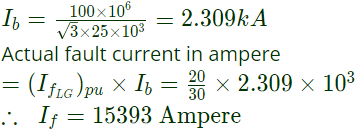
Q19: A three phase, 100 MVA, 25 kV generator has solidly grounded neutral. The positive, negative, and the zero sequence reactances of the generator are 0.2 pu, 0.2 pu and 0.05 pu, respectively, at the machine base quantities. If a bolted single phase to ground fault occurs at the terminal of the unloaded generator, the fault current in amperes immediately after the fault is_____. (SET-2 (2014))
(a) 15393
(b) 25528
(c) 10547
(d) 35000
Ans: (a)
Sol: 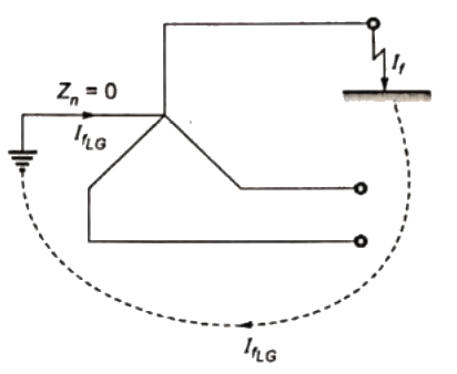 Given, X1 = 0.2pu, X2 = 0.2pu, X3 = 0.05pu
For a line-to-ground fault on generator, fault current is given by
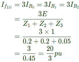 Also, base MVA = 100
Base KVA = 25
Theerefore, Base current,
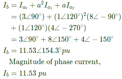
Q20: In an unbalanced three phase system, phase current Ia = 1∠ −90° pu, negative sequence current Ib2 = 4∠(−150°) zero sequence current Ic0 = 3∠ −90° pu. The magnitude of phase current Ib in pu is (SET-1(2014))
(a) 1
(b) 7.81
(c) 11.53
(d) 13
Ans: (c)
Sol: Given,
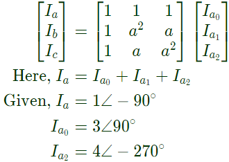
Ia = 1∠(−90°)pu
Ib = 4∠(−150°)pu
Ic = 3∠(90°)pu
As zero sequence current in all the three phases of unbalanced 3 − ϕ system are equal, therefore,

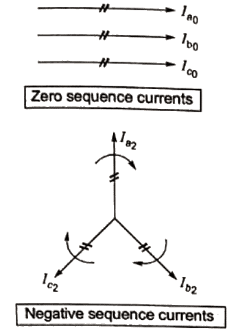 Also,
Also,  = 4∠−150°
= Negative phase sequence current of phase b.
Therefore, referring to the negative phase sequence phasor,
 = 4∠(−150° − 120°) = 4∠ − 270°pu
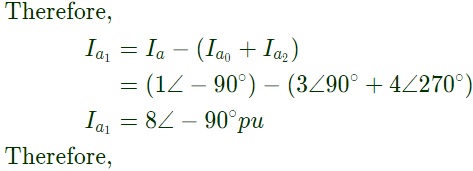
We know that, phase current vectors in matrix form are given by
 (a) 0.25
 A1 = A2


 (a) 7.22
 From negative sequence network :
 For L − L fault,


 SC MVA = 20 x 5 = 100 MVA
 (a) 60
 The first term of expression indicates DC offset current.


 If the positive sequence impedance is (1 + j10)Ω, and the zero sequence is (4 + j31)Ω, then the imaginary part of Zm (in Ω) is ______(up to 2 decimal places). (2018)
 we know.
 The imaginary part of Zm is 7.00.

 (a) 4.5


 (a) 2.28


 (a) VAB leads Vab by 60°


 (a) Location P
 Given, X1 = 0.2pu, X2 = 0.2pu, X3 = 0.05pu
 Also, base MVA = 100

 Also,
Also,  = 4∠−150°
 = 4∠(−150° − 120°) = 4∠ − 270°pu


