Previous Year Questions- Load Flow Studies - 2 | Power Systems - Electrical Engineering (EE) PDF Download
Q21: In the following network, the voltage magnitudes at all buses are equal to 1 p.u., the voltage phase angles are very small, and the line resistances are negligible. All the line reactances are equal to j1Ω.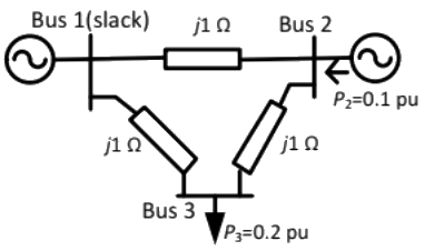 If the base impedance and the line-to line base voltage are 100 Ω and 100 kV respectively, then the real power in MW delivered by the generator connected at the slack bus is (2013)
(a) -10
(b) 0
(c) 10
(d) 20
Ans: (c)
Sol: P1 = 0.1p.u.
Q22: In the following network, the voltage magnitudes at all buses are equal to 1 p.u., the voltage phase angles are very small, and the line resistances are negligible. All the line reactances are equal to j1Ω.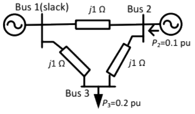 The voltage phase angles in rad at buses 2 and 3 are (2013)
(a) θ2 = −0.1, θ3 = −0.2
(b) θ2 = 0, θ3 = −0.1
(c) θ2 = 0.1, θ3 = 0.1
(d) θ2 = 0.1, θ3 = 0.2
Ans: (b)
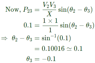
Sol: 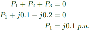 No power flow in between bus 1 and 2.
 As bus 1 is a slack bus
Q23: A single-phase load is supplied by a single-phase voltage source. If the current flowing from the load to the source is 10∠ −150°A and if the voltage at the load terminal is 100∠60°V, then the (2013)
(a) load absorbs real power and delivers reactive power
(b) load absorbs real power and absorbs reactive power
(c) load delivers real power and delivers reactive power
(d) load delivers real power and absorbs reactive power
Ans: (b)
Sol: 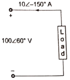 Complex power supplied by load = (100∠60°)(10∠ −150°) = −866.022 − j500VA
As supplied active and reactive power are negative.
Load absorbs active and reactive power both.
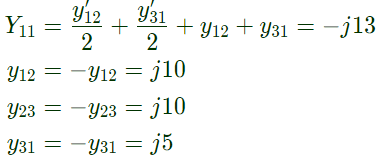
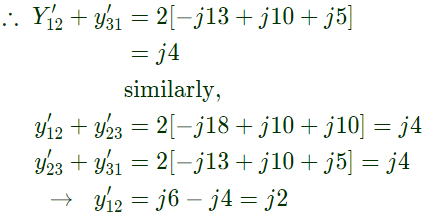
Q24: The bus admittance matrix of a three-bus three-line system is If each transmission line between the two buses is represented by an equivalent π-network, the magnitude of the shunt susceptance of the line connecting bus 1 and 2 is (2012)
(a) 4
(b) 2
(c) 1
(d) 0
Ans: (b)
Sol: yik= Series admittance of the line connecting buses I and k
y'ik/2 = Half line charging admittance in bus admittance matrix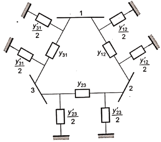
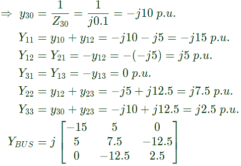
Q25: A three-bus network is shown in the figure below indicating the p.u. impedance of each element.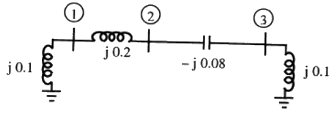 The bus admittance matrix, Y-bus, of the network is (2011)
(a)  (b)
(b)  (c)
(c)  (d)
(d)  Ans: (b)
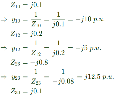
Sol: 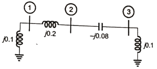
Q26: Consider two buses connected by an impedence of (0 + j5)Ω. The bus 1 voltage is 100∠30° V, and bus 2 voltage is 100∠0° V. The real and reactive power supplied by bus 1 respectively are (2010)
(a) 1000 W, 268 VAr
(b) -1000 W, -134 VAr
(c) 276.9 W, -56.7 VAr
(d) -276.9 W, 56.7 VAr
Ans: (a)
Sol: V1 = 100∠30°V
V2 = 100∠0°V
as δ1 > δ2, current will flow from bus 1 to bus 2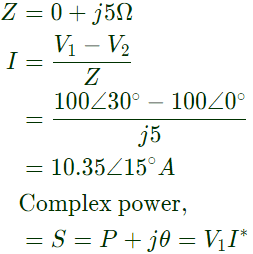

Q27: For the Y-bus matrix of a 4-bus system given in per unit, the buses having shunt elements are (2009)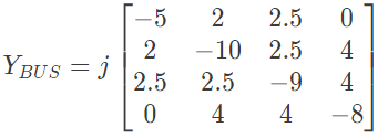 (a) 3 and 4
(b) 2 and 3
(c) 1 and 2
(d) 1, 2 and 4
Ans: (c)
Sol: 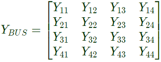 Here,
Here,
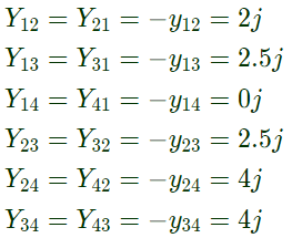 From equation (i),
 From equation (ii),
 From equation (iii),
 From equation (iv),
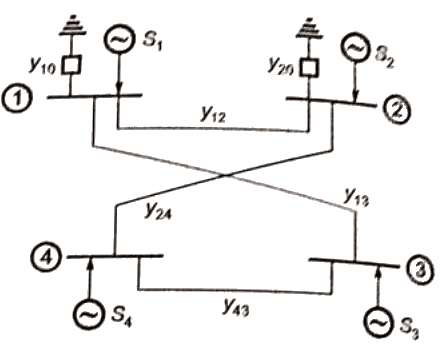
Q28: Consider the two power systems shown in figure A below, which are initially not interconnected, and are operating in steady state at the same frequency. Separate load flow solutions are computed individually of the two systems, corresponding to this scenario. The bus voltage phasors so obtain are indicated on figure A. These two isolated systems are now interconnected by a short transmission line as shown in figure B, and it is found that P1 = P2 = Q1 = Q2 = 0.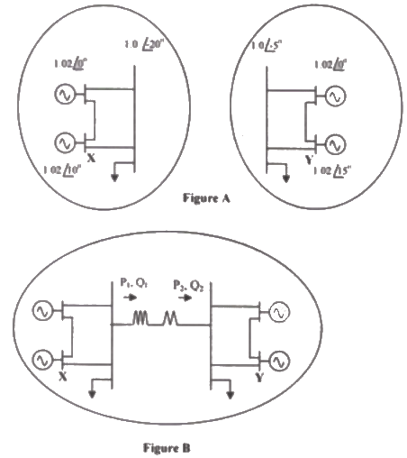 The bus voltage phase angular difference between generator bus X and generator bus Y after interconnection is (2007)
(a) 10°
(b) 25°
(c) -30°
(d) 30°
Ans: (a)
Sol: Flow of power in transmission line depends on bus voltage magnitude and phase difference between bus voltage.
After interconnecting the two system by a line there is no power flow in the line hence bus voltage magnitude and phase difference between buses will remain same as before interconnecting the two systems.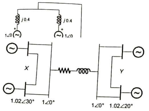 Phase difference between bus X and bus Y = 30 − 20 = 10°
Q29: For a power System the admittance and impedance matrices for the fault studies are as fallows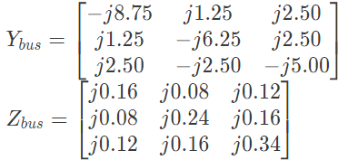 The pre-fault voltages are 1.0 pu. at all the buses. The system was unloaded prior to the fault. A solid 3-phase fault takes place at bus 2.
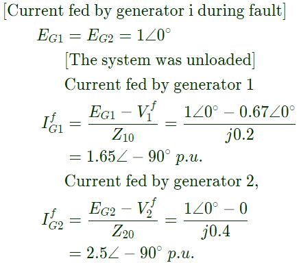
The per unit fault feeds from generators connected to buses 1 and 2 respectively are (2006)
(a) 1.20, 2.51
(b) 1.55, 2.61
(c) 1.66, 2.50
(d) 5.00, 2.50
Ans: (c)
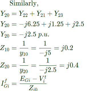
Sol: Yii = Sum of the admittance directly connected to ith bus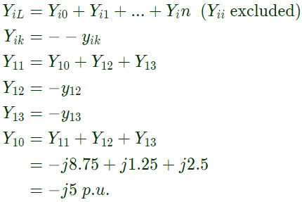
Q30: For a power system the admittance and impedance matrices for the fault studies are as fallows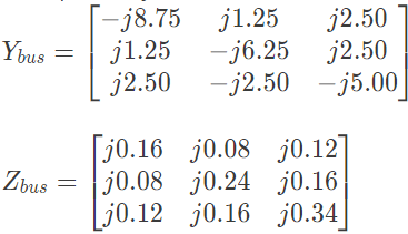 The pre-fault voltages are 1.0 pu. at all the buses. The system was unloaded prior to the fault. A solid 3-phase fault takes place at bus 2.
The post fault voltages at buses 1 and 3 in per unit respectively are (2006)
(a) 0.24, 0.63
(b) 0.31, 0.76
(c) 0.33, 0.67
(d) 0.67, 0.33
Ans: (d)
Sol: 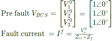 Solid 3 − ϕ fault occurs at bus 2, r = 2 and
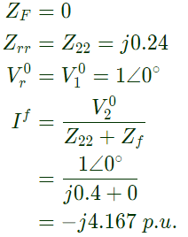 Post fault voltage at bus i is given by
 Post fault voltage at bus, i = 1
 Post fault voltage at bus, i = 3
Q31: The Gauss Seidel load flow method has following disadvantages. Tick the incorrect statement (2006)
(a) Unreliable convergence
(b) Slow convergence
(c) Choice of slack bus affects convergence
(d) A good initial guess for voltages is essential for convergence
Ans: (d)
Sol: The G.S. method has following disadvantage:
unreliable convergence
slow convergence
sensitivity to the choise of slack bus.
Q32: The network shown in the given figure has impedances in p.u. as indicated. The diagonal element Y22 of the bus admittance matrix YBUS of the network is (2005)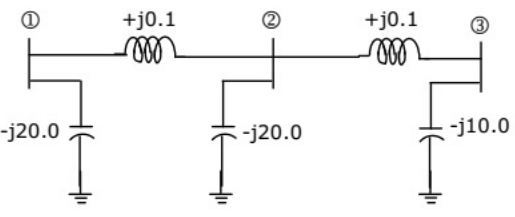 (a) -j19.8
(b) +j20.0
(c) +j0.2
(d) -j19.95
Ans: (d)
Sol: Impedance between bus (1) and bus (2) = Z12 = j0.1
admittance 
Impedance between bus (2) and bus (3) = Z23 = j0.1
admittance 
Impedance between bus (2) and bus (0) = Z20 = j20
admittance 

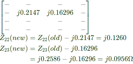
Q33: The bus impedance matrix of a 4-bus power system is given by A branch having an impedance of j0.2Ω is connected between bus 2 and the reference. Then the values of Z22,new and Z23,new of the bus impedance matrix of the modified network are respectively (2003)
(a) j0.5408Ω and j0.4586Ω
(b) j0.1260Ω and j0.0956Ω
(c) j0.5408Ω and j0.0956Ω
(d) j0.1260Ω and 0.1630Ω
Ans: (b)
Sol:  New elements (ZB) is connected between jth and reference bus.
Here, j = 2, b = 4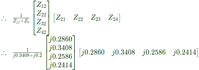 We are required only changes in Z22Z23
Q34: A power system consist of 300 buses out of which 20 buses are generator bus, 25 buses are the ones with reactive power support and 15 buses are the ones with fixed shunt capacitors. All the other buses are load buses. It is proposed to perform a load flow analysis in the system using Newton-Raphson method. The size of the Newton Raphson Jacobian matrix is (2003)
(a) 553 x 553
(b) 540 x 540
(c) 555 x 555
(d) 554 x 554
Ans: (d)
Sol: Total buses = 300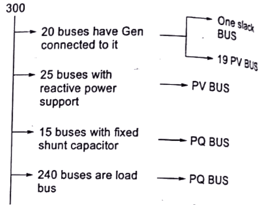 Size of jacobian matrix = No. of unknown bus voltage = 2 × 300 − 2 − 19 − 25 = 554
Q35: A power system consists of 2 areas (Area 1 and Area 2) connected by a single tie line. It is required to carry out a load flow study on this system. While entering the network data, the tie-line data (connectivity and parameters) is inadvertently left out. If the load flow program is run with this incomplete data (2002)
(a) The load-flow will converge only if the slack bus is specified in Area 1
(b) The load-flow will converge only if the slack bus is specified in Area 2
(c) The load-flow will converge if the slack bus is specified in either Area 1 or Area 2
(d) The load-flow will not converge if only one slack bus is specified.
Ans: (d)
Sol: For load flow study to converge there must be one slack bus in the system. As while entering the network data the tie-line data is not considered, two areas will now be treated as separate areas, hence, two slack bus (one in each area) is required.
|
21 videos|69 docs|45 tests
|


