
Best Study Material for Electrical Engineering (EE) Exam
Electrical Engineering (EE) Exam > Electrical Engineering (EE) Notes > Control Systems > Previous Year Questions- Time Response Analysis - 2
Previous Year Questions- Time Response Analysis - 2 | Control Systems - Electrical Engineering (EE) PDF Download
Q16: A two loop position control system is shown below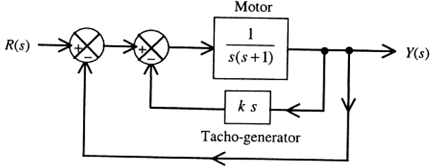 The gain K of the Tacho-generator influences mainly the (2011)
(a) Peak overshoot
(b) Natural frequency of oscillation
(c) Phase shift of the closed loop transfer function at very low frequencies (ω → 0)
(d) Phase shift of the closed loop transfer function at very high frequencies (ω → ∞)
Ans: (a)
Sol: 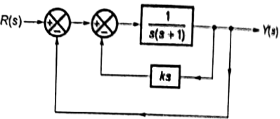
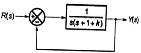 G(s) = 1/s(s+1+k) and H(s) = 1
Characteristic equation 1 + G(s)H(s) = 0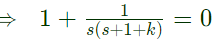 ⇒ s(s + 1 + k) + 1 = 0
⇒ s2 + (R + 1)s + 1 = 0
Comapring with,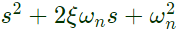 Natural frequency ωn = 1 remains constant and does not depend on k.
2ξωn = k + 1 Damping ratio depends on k
Peak overshoot 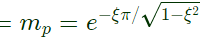
Since, mp depends on ξ which depends on k. Hence, peak overshoot is influenced by gain (k) of techo-generator.
Q17: The steady state error of a unity feedback linear system for a unit step input is 0.1. The steady state error of the same system, for a pulse input r(t) having a magnitude of 10 and a duration of one second, as shown in the figure is (2011)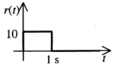 (a) 0
(a) 0
(b) 0.1
(c) 1
(d) 10
Ans: (a)
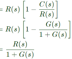
Sol: Let the system is represnted as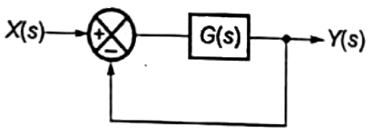
 H(s) = 1(unity feedback)
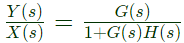
Error = E(s) = X(s)/1+G(s)
Steady state error for X(s) = 1/s, ess = 0.1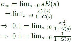 When input,
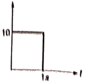 X(t) = 10[u(t) − u(t − 1)]
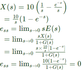
Q18: For the system 2/(s + 1), the approximate time taken for a step response to reach 98% of the final value is (2010)
(a) 1s
(b) 2s
(c) 4s
(d) 8s
Ans: (c)
Sol: 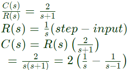 C(t) = L−1[C(s)]=2[−1 − e−t]
Final value of C(t) = Css = 2
98% of Css = 0.98 × 2 = 1.96
Let, t = T, the response reaches 98% of its final values.
1.96 = 2[1 − e−T]
T ≈ 4sec
Q19: The unit-step response of a unity feed back system with open loop transfer function G(s) = K/((s + 1) (s + 2)) is shown in the figure. The value of K is (2009)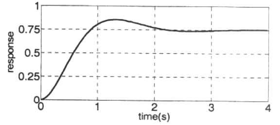 (a) 0.5
(b) 2
(c) 4
(d) 6
Ans: (d)
Sol: Steady state value of response = 0.75
Input is unit step
So steady state error
ess = 1 − 0.75 = 0.25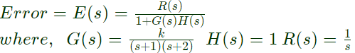 Steady state erro using find value theorem,
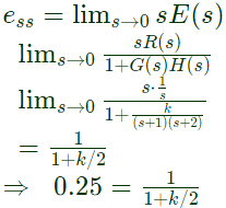 ⇒ k = 6
Q20: The transfer function of a system is given as 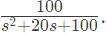 This system is (2008)
(a) An over damped system
(b) An under damped system
(c) A critically damped system
(d) An unstable system
Ans: (c)
Sol: 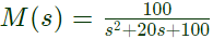 Comparing with standard form,
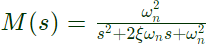 ∴ 2ξωn = 20
ω2n = 100
ξ = 1
ωn = 10
∴ The system is critically damped.
Q21: The transfer function of a linear time invariant system is given as 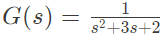 The steady state value of the output of the system for a unit impulse input applied at time instant t = 1 will be (2008)
(a) 0
(b) 0.5
(c) 1
(d) 2
Ans: (a)
Sol: r(t) = unit impulse applied at t = 1
= δ(t − 1)
R(s) = 1[r(t)] = e−s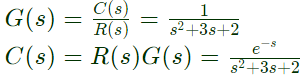 Steady state value of output, using final value theoram,
Css = lims→0 sC(s) 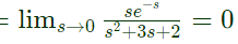
Q22: Consider the R-L-C circuit shown in figure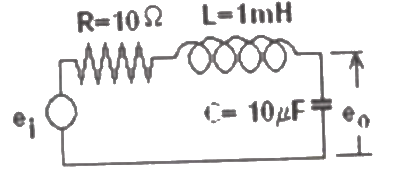 If the above step response is to be observed on a non-storage CRO, then it would be best have the ei as a (2007)
(a) Step function
(b) Square wave of 50 Hz
(c) Square wave of 300 Hz
(d) Square wave of 2.0 KHz
Ans: (c)
Sol:  Settling time
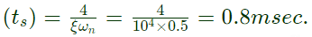
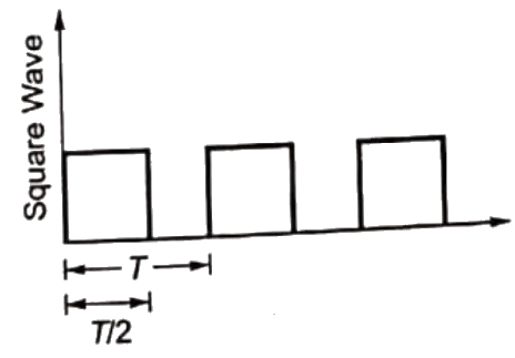 For a square wave T/2 should be grater than ts
For f1 = 50Hz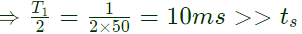 For f2 = 300Hz
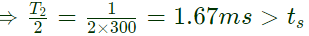 For f3 = 2kHz
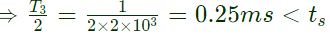 Therefore, it would be best to have ei as a square wave of 300Hz.
Q23: Consider the R-L-C circuit shown in figure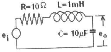 For a step-input ei, the overshoot in the output eo will be (2007)
(a) 0, since the system is not under damped
(b) 5%
(c) 16%
(d) 48%
Ans: (c)
Sol: 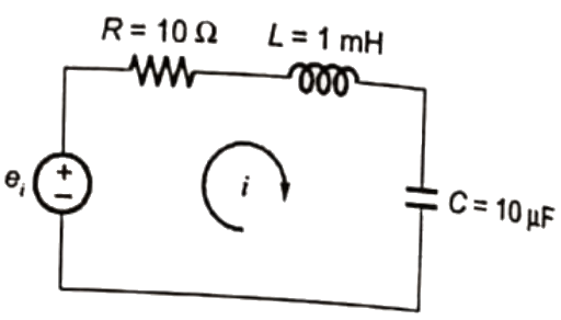
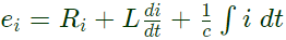 Taking Laplace transform,
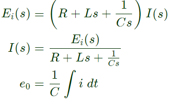
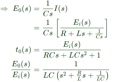 Characteristic equation,
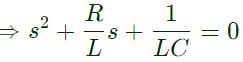 Comparing with,
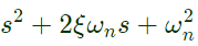
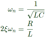
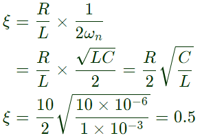 Overshot
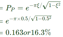
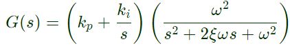
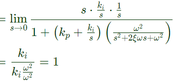
Q24: Consider the feedback system shown below which is subjected to a unit step input. The system is stable and has following parameters kp = 4, ki = 10, ω = 500 and ξ = 0.7. The steady state value of z is (2007)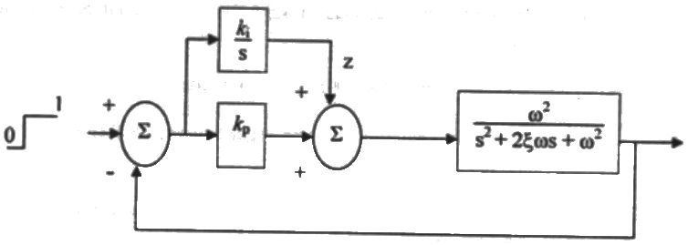 (a) 1
(a) 1
(b) 0.25
(c) 0.1
(d) 0
Ans: (a)
Sol: Step−input ⇒ R(s) = 1/s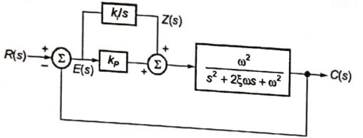
 and H(s) = 1
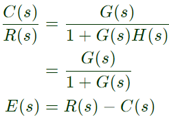
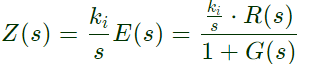 Steady state value of Z,
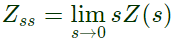
Q25: The block diagram of a closed loop control system is given by figure. The values of K and P such that the system has a damping ratio of 0.7 and an undamped natural frequency ωn of 5 rad/sec, are respectively equal to (2004)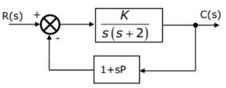 (a) 20 and 0.3
(b) 20 and 0.2
(c) 25 and 0.3
(d) 25 and 0.2
Ans: (d)
Sol: 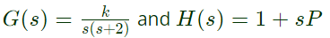 Closed-loop transfer function,
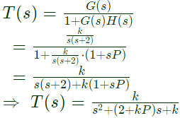 So, characteristic equation = s2 + (2 + kP)s + k
Comparing with standard equation 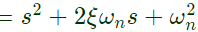
 (where ωn = undamped natueal frequency)
2ξωn = 2 + kP
⇒ 2 × 0.7 × 5 = 2 + 25P
(where ξ = damping ratio)
P = 0.2
Q26: The block diagram shown in figure gives a unity feedback closed loop control system. The steady state error in the response of the above system to unit step input is (2003)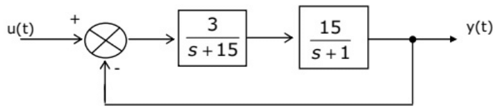 (a) 25%
(b) 0.75%
(c) 6%
(d) 33%
Ans: (a)
Sol: 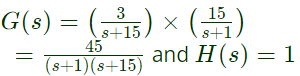 Open loop transfer function
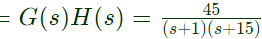
The system is type-0.
Steady state error to unit-step input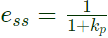 where,
kp = Position error constant = lims→0 G(s)H(s)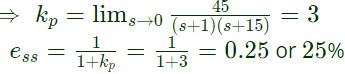
The document Previous Year Questions- Time Response Analysis - 2 | Control Systems - Electrical Engineering (EE) is a part of the Electrical Engineering (EE) Course Control Systems.
All you need of Electrical Engineering (EE) at this link: Electrical Engineering (EE)
|
54 videos|83 docs|40 tests
|


FAQs on Previous Year Questions- Time Response Analysis - 2 - Control Systems - Electrical Engineering (EE)
| 1. What is time response analysis? |  |
| 2. What are the key parameters to consider in time response analysis? | |
Ans. The key parameters to consider in time response analysis include rise time, settling time, peak time, peak overshoot, and steady-state error. These parameters help in evaluating the performance of a control system.
| 3. How is the settling time of a system determined in time response analysis? | |
Ans. The settling time of a system is the time it takes for the system's response to reach and stay within a specified range around its final value without oscillating. It is typically measured as the time taken for the response to settle within a certain percentage (e.g., 5%) of the final value.
| 4. What is the significance of peak time in time response analysis? | |
Ans. Peak time is the time taken for the response of a system to reach the peak value or overshoot before settling down. It is an important parameter as it indicates how quickly the system responds to a change in input.
| 5. How does time response analysis help in designing and analyzing control systems? | |
Ans. Time response analysis helps in designing and analyzing control systems by providing insights into the system's dynamic behavior, stability, and performance. It allows engineers to optimize the system's response to achieve desired specifications and improve overall system efficiency.
About this Document

4.81/5
Rating

Apr 26, 2025
Last updated
Document Description: Previous Year Questions- Time Response Analysis - 2 for Electrical Engineering (EE) 2025 is part of Control Systems preparation.
The notes and questions for Previous Year Questions- Time Response Analysis - 2 have been prepared according to the Electrical Engineering (EE) exam syllabus. Information about Previous Year Questions- Time Response Analysis - 2 covers topics
like and Previous Year Questions- Time Response Analysis - 2 Example, for Electrical Engineering (EE) 2025 Exam. Find important definitions, questions, notes, meanings, examples, exercises and tests below for Previous Year Questions- Time Response Analysis - 2.
Introduction of Previous Year Questions- Time Response Analysis - 2 in English is available as part of our Control Systems
for Electrical Engineering (EE) & Previous Year Questions- Time Response Analysis - 2 in Hindi for Control Systems course.
Download more important topics related with notes, lectures and mock test series for Electrical Engineering (EE)
Exam by signing up for free. Electrical Engineering (EE): Previous Year Questions- Time Response Analysis - 2 | Control Systems - Electrical Engineering (EE)
Description
Full syllabus notes, lecture & questions for Previous Year Questions- Time Response Analysis - 2 | Control Systems - Electrical Engineering (EE) - Electrical Engineering (EE) | Plus excerises question with solution to help you revise complete syllabus for Control Systems | Best notes, free PDF download
Information about Previous Year Questions- Time Response Analysis - 2
In this doc you can find the meaning of Previous Year Questions- Time Response Analysis - 2 defined & explained in the simplest way possible. Besides explaining types of
Previous Year Questions- Time Response Analysis - 2 theory, EduRev gives you an ample number of questions to practice Previous Year Questions- Time Response Analysis - 2 tests, examples and also practice Electrical Engineering (EE)
tests
Top Courses for Electrical Engineering (EE)

Related Searches
Viva Questions
,study material
,past year papers
,Free
,Exam
,Important questions
,Summary
,practice quizzes
,MCQs
,Sample Paper
,Objective type Questions
,video lectures
,Semester Notes
,Previous Year Questions with Solutions
,Previous Year Questions- Time Response Analysis - 2 | Control Systems - Electrical Engineering (EE)
,Extra Questions
,mock tests for examination
,ppt
,Previous Year Questions- Time Response Analysis - 2 | Control Systems - Electrical Engineering (EE)
,Previous Year Questions- Time Response Analysis - 2 | Control Systems - Electrical Engineering (EE)
,shortcuts and tricks
;


Additional Information about Previous Year Questions- Time Response Analysis - 2 for Electrical Engineering (EE) Preparation
Previous Year Questions- Time Response Analysis - 2 Free PDF Download
The Previous Year Questions- Time Response Analysis - 2 is an invaluable resource that delves deep into the core of the Electrical Engineering (EE) exam.
These study notes are curated by experts and cover all the essential topics and concepts, making your preparation more efficient and effective.
With the help of these notes, you can grasp complex subjects quickly, revise important points easily,
and reinforce your understanding of key concepts. The study notes are presented in a concise and easy-to-understand manner,
allowing you to optimize your learning process. Whether you're looking for best-recommended books, sample papers, study material,
or toppers' notes, this PDF has got you covered. Download the Previous Year Questions- Time Response Analysis - 2 now and kickstart your journey towards success in the Electrical Engineering (EE) exam.
Importance of Previous Year Questions- Time Response Analysis - 2
The importance of Previous Year Questions- Time Response Analysis - 2 cannot be overstated, especially for Electrical Engineering (EE) aspirants.
This document holds the key to success in the Electrical Engineering (EE) exam.
It offers a detailed understanding of the concept, providing invaluable insights into the topic.
By knowing the concepts well in advance, students can plan their preparation effectively.
Utilize this indispensable guide for a well-rounded preparation and achieve your desired results.
Previous Year Questions- Time Response Analysis - 2 Notes
Previous Year Questions- Time Response Analysis - 2 Notes offer in-depth insights into the specific topic to help you master it with ease.
This comprehensive document covers all aspects related to Previous Year Questions- Time Response Analysis - 2.
It includes detailed information about the exam syllabus, recommended books, and study materials for a well-rounded preparation.
Practice papers and question papers enable you to assess your progress effectively.
Additionally, the paper analysis provides valuable tips for tackling the exam strategically.
Access to Toppers' notes gives you an edge in understanding complex concepts.
Whether you're a beginner or aiming for advanced proficiency, Previous Year Questions- Time Response Analysis - 2 Notes on EduRev are your ultimate resource for success.
Previous Year Questions- Time Response Analysis - 2 Electrical Engineering (EE)
The "Previous Year Questions- Time Response Analysis - 2 Electrical Engineering (EE) Questions" guide is a valuable resource for all aspiring students preparing for the
Electrical Engineering (EE) exam. It focuses on providing a wide range of practice questions to help students gauge
their understanding of the exam topics. These questions cover the entire syllabus, ensuring comprehensive preparation.
The guide includes previous years' question papers for students to familiarize themselves with the exam's format and difficulty level.
Additionally, it offers subject-specific question banks, allowing students to focus on weak areas and improve their performance.
Study Previous Year Questions- Time Response Analysis - 2 on the App
Students of Electrical Engineering (EE) can study Previous Year Questions- Time Response Analysis - 2 alongwith tests & analysis from the EduRev app,
which will help them while preparing for their exam. Apart from the Previous Year Questions- Time Response Analysis - 2,
students can also utilize the EduRev App for other study materials such as previous year question papers, syllabus, important questions, etc.
The EduRev App will make your learning easier as you can access it from anywhere you want.
The content of Previous Year Questions- Time Response Analysis - 2 is prepared as per the latest Electrical Engineering (EE) syllabus.
|
© EduRev
|
Education Revolution
|


|


Signup to see your scores
go up within 7 days!
Access 1000+ FREE Docs, Videos and Tests
Takes less than 10 seconds to signup