Electrical Engineering (EE) Exam  >  Electrical Engineering (EE) Notes  >  Electrical and Electronic Measurements  >  Previous Year Questions- Characteristics of Instruments and Measurement Systems

Previous Year Questions- Characteristics of Instruments and Measurement Systems | Electrical and Electronic Measurements - Electrical Engineering (EE) PDF Download

Q1: A non-ideal Si-based pn junction diode is tested by sweeping the bias applied across its terminals from -5 V to +5 V. The effective thermal voltage, VT, for the diode is measured to be (29 ± 2) mV. The resolution of the voltage source in the measurement range is 1 mV. The percentage uncertainty (rounded off to 2 decimal plates) in the measured current at a bias voltage of 0.02 V is _______.  (2020)
(a) 5.87
(b) 2.35
(c) 11.5
(d) 9.2
Ans:
(c)

Q2: Two resistors with nominal resistance values R1 and R2 have additive uncertainties ΔR1 and ΔR2, respectively. When these resistances are connected in parallel, the standard deviation of the error in the equivalent resistance R is  (SET-2 (2017))
(a) Previous Year Questions- Characteristics of Instruments and Measurement Systems | Electrical and Electronic Measurements - Electrical Engineering (EE)

(b) Previous Year Questions- Characteristics of Instruments and Measurement Systems | Electrical and Electronic Measurements - Electrical Engineering (EE)
(c) Previous Year Questions- Characteristics of Instruments and Measurement Systems | Electrical and Electronic Measurements - Electrical Engineering (EE)
(d) Previous Year Questions- Characteristics of Instruments and Measurement Systems | Electrical and Electronic Measurements - Electrical Engineering (EE)
Ans: (a)
Sol: Previous Year Questions- Characteristics of Instruments and Measurement Systems | Electrical and Electronic Measurements - Electrical Engineering (EE)Previous Year Questions- Characteristics of Instruments and Measurement Systems | Electrical and Electronic Measurements - Electrical Engineering (EE)
Q3: The following measurements are obtained on a single phase load:
V = 220V ± 1%, I = 5.0A ± 1% and W = 555W ± 2%.
If the power factor is calculated using these measurements, the worst case error in the calculated power factor in percent is ________.  (SET-1(2017))
(a) 20%
(b) 40%
(c) 4%
(d) 0.40%
Ans:
(c)
Sol: V = 220 ± 1%
I = 5 ± 1%
W = 555 ± 2%
W = VI cos(∅)
p.f. = cos(∅) = (W/VI)
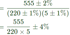
Previous Year Questions- Characteristics of Instruments and Measurement Systems | Electrical and Electronic Measurements - Electrical Engineering (EE)p.f. = 0.5 ± 4%

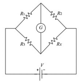
Q4: When the Wheatstone bridge shown in the figure is used to find the value of resistor RX, the galvanometer G indicates zero current when R1 = 50Ω, R2 = 65Ω and R= 100Ω. If Ris known with ±5% tolerance on its nominal value of 100 Ω , what is the range of RX in Ohms? (SET-1 (2015))
Previous Year Questions- Characteristics of Instruments and Measurement Systems | Electrical and Electronic Measurements - Electrical Engineering (EE)(a) [123.50, 136.50]
(b) [125.89, 134.12]
(c) [117.00, 143.00]
(d) [120.25, 139.75]
Ans:
(a)
Sol: R= 50Ω
R= 60Ω
R= 100 ± 5
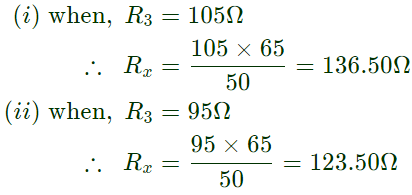
The value of R3 with ±5% of tollerance,
R3 = 100 ± 5%
= 100 + 100 × (5/100) = 105Ω
= 100 − 100 × (5/100) = 95Ω
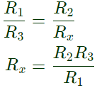
In both condition, the bridge is balance, so under balance condition,
Previous Year Questions- Characteristics of Instruments and Measurement Systems | Electrical and Electronic Measurements - Electrical Engineering (EE)Previous Year Questions- Characteristics of Instruments and Measurement Systems | Electrical and Electronic Measurements - Electrical Engineering (EE)
Q5: The measurement system shown in the figure uses three sub-systems in cascade whose gains are specified as G1, G2 and (1/G3). The relative small errors associated with each respective subsystem G1, G2 and G3 are ε1, ε2 and ε3. The error associated with the output is : (2009)
Previous Year Questions- Characteristics of Instruments and Measurement Systems | Electrical and Electronic Measurements - Electrical Engineering (EE)(a) ε1+ε2+1/ε3ε1 + ε+ 1/ε3
(b) ε1ε23
(c) ε1+ε2ε3ε+ ε2 − ε3 
(d) ε1+ε2+ε3ε1 + ε2 + ε3 
Ans: 
(c)
Sol: Previous Year Questions- Characteristics of Instruments and Measurement Systems | Electrical and Electronic Measurements - Electrical Engineering (EE)where, x = input
ln⁡ y = ln⁡ G+ ln⁡ G2−ln⁡ G3 + ln⁡ x
Differentiating both side,
Previous Year Questions- Characteristics of Instruments and Measurement Systems | Electrical and Electronic Measurements - Electrical Engineering (EE)No error is specified in input, so (dx/x) = 0
dy/y = ε1 + ε2 − ε3

Q6: A variable w is related to three other variables x, y, z as w = xy/z. The variables are measured with meters of accuracy ±0.5% reading,  ±1% of full scale value and ±1.5% reading. The actual readings of the three meters are 80, 20 and 50 with 100 being the full scale value for all three. The maximum uncertainty in the measurement of w will be (2006)
(a) ±0.5% rdg
(b) ±5.5% rdg
(c) ±6.7% rdg
(d) ±7.0% rdg
Ans: 
(d)
Sol: Full scale reading of all three = 100
Reading of x = 80
Reading of y = 20
Reading of z = 50
δx = ±0.5% of reading Previous Year Questions- Characteristics of Instruments and Measurement Systems | Electrical and Electronic Measurements - Electrical Engineering (EE)
δy = ±1% of reading Previous Year Questions- Characteristics of Instruments and Measurement Systems | Electrical and Electronic Measurements - Electrical Engineering (EE)
δz = ±1.5% of reading Previous Year Questions- Characteristics of Instruments and Measurement Systems | Electrical and Electronic Measurements - Electrical Engineering (EE)
Given ω = xy/z
taking log, we get,
log⁡ω = log⁡x + log⁡y − log⁡z
differenting w.r.t. ω we get  
Previous Year Questions- Characteristics of Instruments and Measurement Systems | Electrical and Electronic Measurements - Electrical Engineering (EE)For maximum limiting error,
Previous Year Questions- Characteristics of Instruments and Measurement Systems | Electrical and Electronic Measurements - Electrical Engineering (EE)
Q7: Resistances R1 and R2 have, respectively, nominal values of 10Ω and 5Ω, and tolerances of ±5 % and ±10%. The range of values for the parallel combination of R1 and R2 is  (2001)
(a) 3.077 Ω to 3.636 Ω
(b) 2.805 Ω to 3.371 Ω
(c) 3.237 Ω to 3.678 Ω
(d) 3.192 Ω to 3.435 Ω
Ans:
(a)
Sol: Range of R1 = 10 ± 10 × (5/100)
= 9.5Ω to 10.5Ω
Range of R2 = 5 ± 5 × (10/100)
= 4.5Ω to 5.5Ω
Previous Year Questions- Characteristics of Instruments and Measurement Systems | Electrical and Electronic Measurements - Electrical Engineering (EE)= 3.05Ω to 3.61Ω  

The document Previous Year Questions- Characteristics of Instruments and Measurement Systems | Electrical and Electronic Measurements - Electrical Engineering (EE) is a part of the Electrical Engineering (EE) Course Electrical and Electronic Measurements.
All you need of Electrical Engineering (EE) at this link: Electrical Engineering (EE)
3 videos|39 docs|22 tests

Top Courses for Electrical Engineering (EE)

FAQs on Previous Year Questions- Characteristics of Instruments and Measurement Systems - Electrical and Electronic Measurements - Electrical Engineering (EE)

1. What are the main characteristics of electrical measurement instruments?
Ans.The main characteristics of electrical measurement instruments include accuracy, precision, sensitivity, range, resolution, and linearity. Accuracy refers to how close a measurement is to the true value, while precision indicates the repeatability of measurements. Sensitivity is the ability of an instrument to detect small changes in measurement. Range defines the limits within which the instrument can operate, and resolution is the smallest change that can be detected by the instrument. Linearity describes how well the instrument's output corresponds to the input over its entire range.
2. How do you differentiate between accuracy and precision in measurement systems?
Ans.Accuracy and precision are often confused but they are distinct concepts. Accuracy refers to how close a measured value is to the actual (true) value, while precision refers to the consistency of repeated measurements. An instrument can be precise but not accurate if it consistently measures the same value that is far from the true value. Conversely, an instrument can be accurate but not precise if it provides measurements that vary widely from one another but are close to the true value on average.
3. What factors affect the sensitivity of a measurement instrument?
Ans.Factors that affect the sensitivity of a measurement instrument include the design of the instrument, the type of sensor used, environmental conditions, and the calibration of the instrument. The inherent design of the instrument and the materials used in the sensor can greatly influence how small a change in the input signal can be detected. Additionally, external conditions such as temperature, humidity, and electromagnetic interference can also impact sensitivity, as can the calibration process that ensures the instrument is providing accurate measurements.
4. What is the significance of calibration in measurement systems?
Ans.Calibration is crucial in measurement systems because it ensures that the instrument provides accurate and reliable measurements. Calibration involves comparing the measurements of an instrument to a known standard and making adjustments as necessary. This process helps identify any systematic errors and corrects them, ensuring that the instrument maintains its accuracy over time. Regular calibration is essential for compliance with industry standards and for maintaining the credibility of measurement results in scientific and engineering applications.
5. Can you explain the concept of resolution in the context of electrical measurement?
Ans.Resolution in electrical measurement refers to the smallest change in the measured quantity that can be detected by the instrument. It is often determined by the least significant digit displayed by the instrument and is crucial for understanding the instrument's ability to differentiate between small variations in measurements. Higher resolution indicates that the instrument can detect and display smaller differences, which is particularly important in applications that require fine measurements, such as in laboratory experiments and precision engineering tasks.
3 videos|39 docs|22 tests
Download as PDF
Explore Courses for Electrical Engineering (EE) exam

Top Courses for Electrical Engineering (EE)

Signup for Free!
Signup to see your scores go up within 7 days! Learn & Practice with 1000+ FREE Notes, Videos & Tests.
10M+ students study on EduRev
Related Searches

Previous Year Questions with Solutions

,

study material

,

Important questions

,

video lectures

,

Exam

,

Summary

,

shortcuts and tricks

,

Semester Notes

,

pdf

,

mock tests for examination

,

MCQs

,

Extra Questions

,

Previous Year Questions- Characteristics of Instruments and Measurement Systems | Electrical and Electronic Measurements - Electrical Engineering (EE)

,

Viva Questions

,

past year papers

,

Free

,

Previous Year Questions- Characteristics of Instruments and Measurement Systems | Electrical and Electronic Measurements - Electrical Engineering (EE)

,

Sample Paper

,

Previous Year Questions- Characteristics of Instruments and Measurement Systems | Electrical and Electronic Measurements - Electrical Engineering (EE)

,

Objective type Questions

,

practice quizzes

,

ppt

;