RC Phase Shift Oscillator | Analog and Digital Electronics - Electrical Engineering (EE) PDF Download
A single stage transistor amplifier can produce 180o of phase shift between its output and input signals when connected as a common-emitter type amplifier and we can use this configuration to produce an RC oscillator circuit.
But we can configure transistor stages to operate as oscillators by placing resistor-capacitor (RC) networks around the transistor to provide the required regenerative feedback without the need for a tank circuit. Frequency selective RC coupled amplifier circuits are easy to build and can be made to oscillate at any desired frequency by selecting the appropriate values of resistance and capacitance.
For an RC oscillator to sustain its oscillations indefinitely, sufficient feedback of the correct phase, that is positive (in-phase) Feedback must be provided along with the voltage gain of the single transistor amplifier being used to inject adequate loop gain into the closed-loop circuit in order to maintain oscillations allowing it to oscillates continuously at the selected frequency.
In an RC Oscillator circuit the input is shifted 180o through the feedback circuit returning the signal out-of-phase and 180o again through an inverting amplifier stage to produces the required positive feedback. This then gives us “180o + 180o = 360o” of phase shift which is effectively the same as 0o, thereby giving us the required positive feedback. In other words, the total phase shift of the feedback loop should be “0” or any multiple of 360o to obtain the same effect.
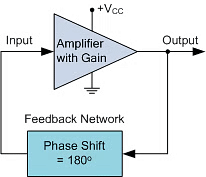
In a Resistance-Capacitance Oscillator or simply known as an RC Oscillator, we can make use of the fact that a phase shift occurs between the input to a RC network and the output from the same network by using interconnected RC elements in the feedback branch, for example.
RC Phase-Shift Network
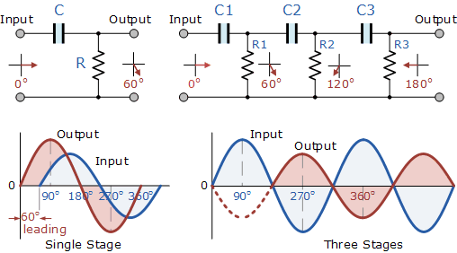
The circuit on the left shows a single resistor-capacitor network whose output voltage “leads” the input voltage by some angle less than 90o. In a pure or ideal single-pole RC network. it would produce a maximum phase shift of exactly 90o, and because 180o of phase shift is required for oscillation, at least two single-poles networks must be used within an RC oscillator design.
However in reality it is difficult to obtain exactly 90o of phase shift for each RC stage so we must therefore use more RC stages cascaded together to obtain the required value at the oscillation frequency. The amount of actual phase shift in the circuit depends upon the values of the resistor (R) and the capacitor (C), at the chosen frequency of oscillations with the phase angle ( φ ) being given as:
RC Phase Angle
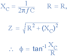
Where: XC is the Capacitive Reactance of the capacitor, R is the Resistance of the resistor, and ƒ is the Frequency.
In our simple example above, the values of R and C have been chosen so that at the required frequency the output voltage leads the input voltage by an angle of about 60o. Then the phase angle between each successive RC section increases by another 60o giving a phase difference between the input and output of 180o (3 x 60o) as shown by the following vector diagram.
Vector Diagram

So by cascading together three such RC networks in series we can produce a total phase shift in the circuit of 180o at the chosen frequency and this forms the bases of a “RC Oscillator” otherwise known as a Phase Shift Oscillator as the phase angle is shifted by an amount through each stage of the circuit. Then the phase shift occurs in the phase difference between the individual RC stages. Conveniently op-amp circuits are available in quad IC packages. For example, the LM124, or the LM324, etc. so four RC stages could also be used to produce the required 180o of phase shift at the required oscillation frequency.
We know that in an amplifier circuit either using a Bipolar Transistor or an Inverting Operational Amplifier configuration, it will produce a phase-shift of 180o between its input and output. If a three-stage RC phase-shift network is connected as a feedback network between the output and input of an amplifier circuit, then the total phase shift created to produce the required regenerative feedback is: 3 x 60o + 180o = 360o = 0o as shown.
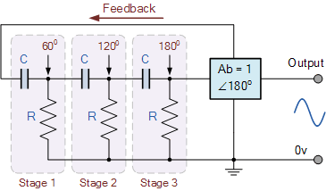
The three RC stages are cascaded together to obtain the required slope for a stable oscillation frequency. The feedback loop phase shift is -180o when the phase shift of each stage is -60o. This occurs when jω = 2piƒ = 1/1.732RC as (tan 60o = 1.732). Then to achieve the required phase shift in an RC oscillator circuit is to use multiple RC phase-shifting networks such as the circuit below.
Basic RC Oscillator Circuit
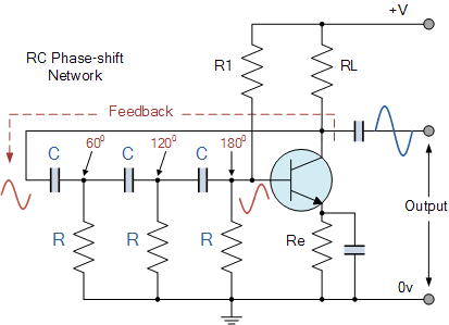
The basic RC Oscillator which is also known as a Phase-shift Oscillator, produces a sine wave output signal using regenerative feedback obtained from the resistor-capacitor (RC) ladder network. This regenerative feedback from the RC network is due to the ability of the capacitor to store an electric charge, (similar to the LC tank circuit).
This resistor-capacitor feedback network can be connected as shown above to produce a leading phase shift (phase advance network) or interchanged to produce a lagging phase shift (phase retard network) the outcome is still the same as the sine wave oscillations only occur at the frequency at which the overall phase-shift is 360o.
By varying one or more of the resistors or capacitors in the phase-shift network, the frequency can be varied and generally this is done by keeping the resistors the same and using a 3-ganged variable capacitor because capacitive reactance (XC) changes with a change in frequency as capacitors are frequency-sensitive components. However, it may be required to re-adjust the voltage gain of the amplifier for the new frequency.
If the three resistors, R are equal in value, that is R1 = R2 = R3, and the capacitors, C in the phase shift network are also equal in value, C1 = C2 = C3, then the frequency of oscillations produced by the RC oscillator is simply given as:

- Where:
- ƒr is the oscillators output frequency in Hertz
- R is the feedback resistance in Ohms
- C is the feedback capacitance in Farads
- N is the number of RC feedback stages.
This is the frequency at which the phase shift circuit oscillates. In our simple example above, the number of stages is given as three, so N = 3 (√2*3 = √6). For a four stage RC network, N = 4 (√2*4 = √8), etc.
Since the resistor-capacitor combination in the RC Oscillator ladder network also acts as an attenuator, that is the signal reduces by some amount as it passes through each passive stage.
It could be assumed that the three phase shift sections are independent of each other but this is not the case as the total accumulative feedback attenuation becomes -1/29th ( Vo/Vi = β = -1/29 ) across all three stages.
Thus the voltage gain of the amplifier must be sufficiently high enough to overcome these passive RC losses. Clearly then in order to produce a total loop gain of -1, in our three stage RC network above, the amplifier gain must be equal too, or greater than, 29 to compensate for the attenuation of the RC network.
The loading effect of the amplifier on the feedback network has an effect on the frequency of oscillations and can cause the oscillator frequency to be up to 25% higher than calculated. Then the feedback network should be driven from a high impedance output source and fed into a low impedance load such as a common emitter transistor amplifier but better still is to use an Operational Amplifier as it satisfies these conditions perfectly.
The Op-amp RC Oscillator
When used as RC oscillators, Operational Amplifier RC Oscillators are more common than their bipolar transistors counterparts. The oscillator circuit consists of a negative-gain operational amplifier and a three section RC network that produces the 180o phase shift. The phase shift network is connected from the op-amps output back to its “inverting” input as shown below.
Op-amp Phase-lead RC Oscillator Circuit
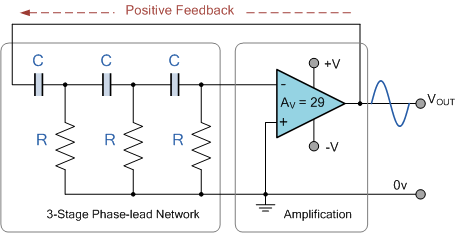
As the feedback is connected to the inverting input, the operational amplifier is therefore connected in its “inverting amplifier” configuration which produces the required 180o phase shift while the RC network produces the other 180o phase shift at the required frequency (180o + 180o). This type of feedback connection with the capacitors in series and the resistors connected to ground (0V) potential is known as a phase-lead configuration. In other words, the output voltage leads the input voltage producing a positive phase angle.
But we can also create a phase-lag configuration by simply changing the positions of the RC components so that the resistors are connected in series and the capacitors are connected to ground (0V) potential as shown. This means that the output voltage lags the input voltage producing a negative phase angle.
Op-amp Phase-lag RC Oscillator Circuit
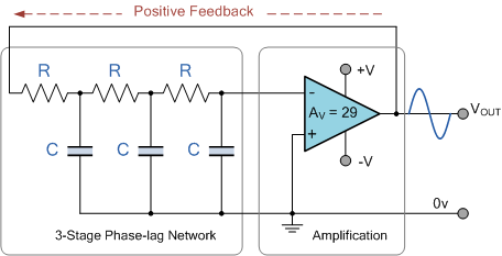
However, due to the reversal of the feedback components, the orginal equation for the frequency output of the phase-lead RC oscillator is modified to:

Although it is possible to cascade together only two single-pole RC stages to provide the required 180o of phase shift (90o + 90o), the stability of the oscillator at low frequencies is generally poor.
One of the most important features of an RC Oscillator is its frequency stability which is its ability to provide a constant frequency sine wave output under varying load conditions. By cascading three or even four RC stages together (4 x 45o), the stability of the oscillator can be greatly improved.
RC Oscillators with four stages are generally used because commonly available operational amplifiers come in quad IC packages so designing a 4-stage oscillator with 45o of phase shift relative to each other is relatively easy.
RC Oscillators are stable and provide a well-shaped sine wave output with the frequency being proportional to 1/RC and therefore, a wider frequency range is possible when using a variable capacitor. However, RC Oscillators are restricted to frequency applications because of their bandwidth limitations to produce the desired phase shift at high frequencies.
RC Oscillator Example No1
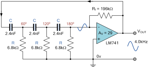
An operational amplifier based 3-stage RC Phase Shift Oscillator is required to produce a sinusoidal output frequency of 4kHz. If 2.4nF capacitors are used in the feedback circuit, calculate the value of the frequency determining resistors and the value of the feedback resistor required to sustain oscillations. Also draw the circuit.
The standard equation given for the phase shift RC Oscillator is:

The circuit is to be a 3-stage RC oscillator which will therefore consist of equal resistors and three equal 2.4nF capacitors. As the frequency of oscillation is given as 4.0kHz, the value of the resistors are calculated as:
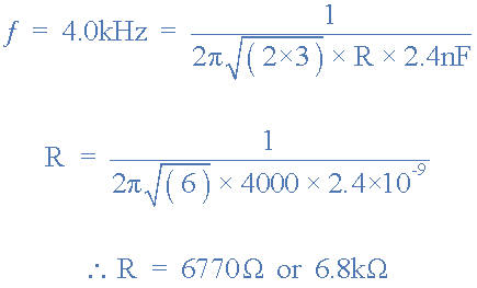
The operational amplifiers gain must be equal to 29 in order to sustain oscillations. The resistive value of the oscillation resistors are 6.8kΩ, therefore the value of the op-amps feedback resistor Rƒ is calculated as:

RC Oscillator Op-amp Circuit
|
137 videos|143 docs|71 tests
|

|
Explore Courses for Electrical Engineering (EE) exam
|

|


