Revision Notes: Electromagnetism | Physics Class 10 ICSE PDF Download

Oersted’s Experiment on the Magnetic Effect of Electric Current
- The following observations were made by Hans Oersted:
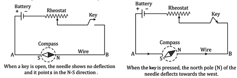
- The experiment suggests that a current-carrying wire produces a magnetic field around it. This is called the magnetic effect of electric current.
Magnetic Field and Field Lines due to a Current in a Straight Conductor
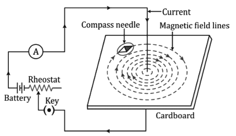
- The magnetic field lines form concentric circles around the wire with their plane perpendicular to the straight wire and with their centres lying on the wire.
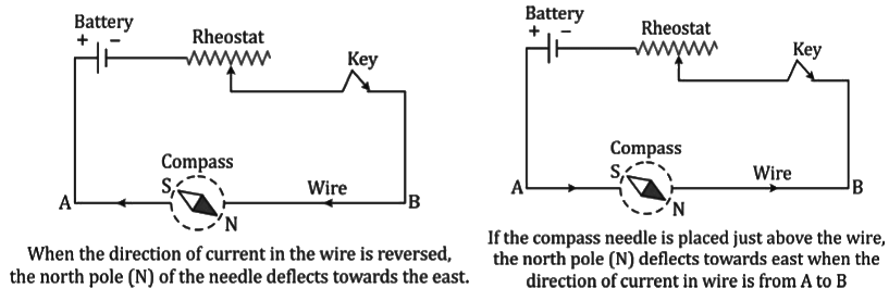
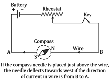
- When the direction of current in the wire is reversed, it is seen that the pattern of iron filings does not change, but the direction of deflection of the compass needle gets reversed.
- On increasing the current in the wire, the magnetic field lines become denser and the iron filings get arranged in circles up to a larger distance from the wire, showing that the magnetic field strength has increased, and so, it is effective up to a larger distance.
Rule to Find the Direction of Magnetic Field
- The direction of magnetic field is given by the right-hand thumb rule.
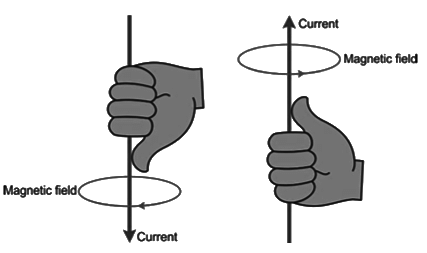
- Imagine that you are holding a current-carrying straight conductor in your right hand such that the thumb points towards the direction of current. Then, your fingers will encircle the conductor in the direction of the field lines of the magnetic field.
Magnetic Field due to Current in a Loop
- When a current is passed through the coil by closing the key and the cardboard is gently tapped, the iron filings get arranged in a definite pattern representing the magnetic field lines due to the current-carrying loop.
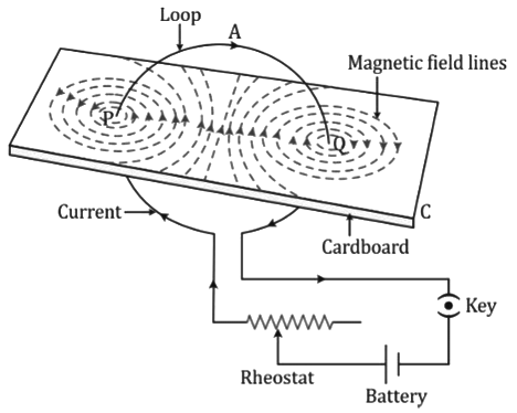
- The direction of the magnetic field at a point is in the direction in which the north pole of the compass needle rests at that point.
- From the pattern of magnetic field lines, it is observed that
i. Near wire at P and Q, the magnetic field lines are nearly circular.
ii. Within the space enclosed by the wire, the magnetic field lines are in the same direction.
iii. Near the centre of the loop, the magnetic field lines are nearly parallel and the magnetic field is assumed to be nearly uniform in a small space near the centre.
iv. At the centre, the magnetic field lines are along the axis of the loop and normal to the plane of the loop.
v. The magnetic field lines become denser if
a. The strength of the current in the loop is increased.
b. The number of turns in the loop is increased. - One face of the loop acts as a north pole because the magnetic field lines emanate from it, and the other face of the loop acts as a south pole because the magnetic field lines enter at it.
- The polarity at the faces of a loop depends on the direction of current in the loop. On reversing the direction of current in the loop, the polarity at the faces of the loop gets reversed.
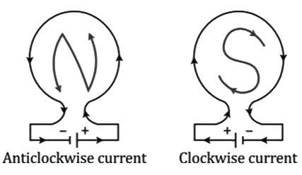
Clock rule (clockwise current - south pole and anticlockwise current - north pole)
- When the current at the face of the loop is anticlockwise, it behaves as the north pole, whereas when the current at the face of the loop is clockwise, it behaves as the south pole.
Magnetic field due to a Cylindrical Coil (or Solenoid)
- When a conducting wire is wound in the form of a cylindrical coil whose diameter is less in comparison to the length, the coil is called a solenoid. It looks like a helical spring.
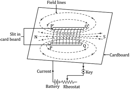
- The direction of the magnetic field at a point can be determined by using a compass needle, and arrows can be marked on these lines in the direction in which the north pole of the compass needle points.
- From this experiment, it is observed that
i. The magnetic field lines inside the solenoid are nearly straight and parallel to the axis of the solenoid.
ii. The magnetic field lines become denser on increasing the current in the solenoid.
iii. The magnetic field is increased if the number of turns in the solenoid of a given length is increased.
iv. The magnetic field is increased if a soft iron core is placed along the axis of the solenoid.
Similarities between a current-carrying solenoid and a bar magnet
- The magnetic field lines of a current-carrying solenoid are similar to the magnetic field lines of a bar magnet.
- A current-carrying solenoid when suspended freely will set itself in the north–south direction exactly in the same manner as a bar magnet.
- A current-carrying solenoid acquires the attractive property of a magnet. When iron filings are brought near the solenoid, it attracts them when current flows through the solenoid.
Dissimilarities between a current-carrying solenoid and a bar magnet
- The magnetic field strength due to a solenoid can be altered by altering the current in it, while the magnetic field strength of a bar magnet cannot be changed.
- The direction of the magnetic field due to a solenoid can be reversed by reversing the direction of the current in it, but the direction of the magnetic field of a bar magnet cannot be changed.
Electromagnet
- An electromagnet is a temporary strong magnet made of a piece of soft iron when current flows in the coil wound around it. It is an artificial magnet.
(a) I-shaped electromagnet (or bar magnet)
- An I-shaped electromagnet is constructed by winding a thin insulated copper wire in the form of a solenoid around a straight soft iron bar. The ends of the wire are connected to a battery through an ammeter, rheostat and key.
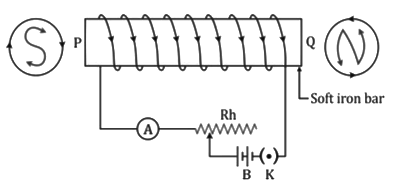
- When current is passed through the winding of a solenoid by closing the key, one end of the bar becomes the South Pole (S) because the current at this face is clockwise, while the other end at which the current is anticlockwise becomes the North Pole (N).
- The soft iron bar acquires magnetic properties only when an electric current flows through the solenoid and loses magnetic properties when the current is switched off; thus, it is a temporary magnet. Such magnets are commonly used in a relay.
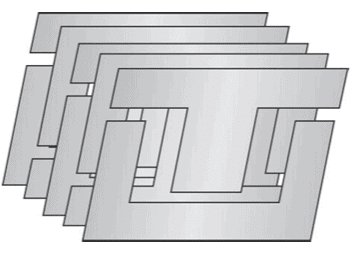
(b) U-shaped (or horseshoe) electromagnet
- To construct a horseshoe electromagnet, a thin insulated copper wire is spirally wound on the arms of a U-shaped soft iron core, such that the winding on the two arms as seen from the ends is in the opposite sense.
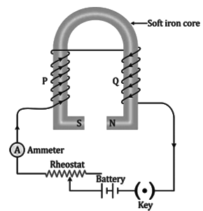
- When current is passed through the winding by closing the key, one end of the arm becomes the South Pole (S) as the current at this face is clockwise, and the other end of the arm becomes the North Pole (N) as the current at this face is anticlockwise.
- Thus, we get a very strong magnetic field in the gap between the two poles. The magnetic field in the gap vanishes as the current in the circuit is switched off. It is also a temporary magnet. Such magnets are used in a DC motor, AC generator etc.
Ways of increasing the magnetic field of an electromagnet
The magnetic field of an electromagnet (I- or U-shaped) can be increased by the following two ways:
- By increasing the number of turns of winding in the solenoid
- By increasing the current through the solenoid
Uses of Electromagnets
Electromagnets are mainly used for the following purposes:- To lift and transport large masses of iron scrap, girders, plates etc.
- To load furnaces with iron.
- To separate magnetic substances such as iron from debris and raw materials.
- To remove pieces of iron from wounds.
- In several electrical devices such as electric bell, telegraph, electric tram, electric motor, relay, microphone, loud speaker etc.
- In scientific research, to study the magnetic properties of a substance in a magnetic field.
Permanent Magnet
- A permanent magnet is a naturally occurring magnet.
- A strong permanent magnet is made of steel instead of soft iron.
- These magnets are used in electric meters (e.g. galvanometer, ammeter, voltmeter) and in a magnetic compass etc.
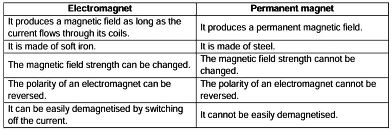
- An electromagnet has the following advantages over a permanent magnet:
- An electromagnet can produce a strong magnetic field.
- The strength of the magnetic field of an electromagnet can easily be changed by changing the current (or the number of turns) in its solenoid.
- The polarity of the electromagnet can be changed by reversing the direction of current in its solenoid.
Use of electromagnet in an electric bell
An electric bell is one of the most commonly used applications of an electromagnet.
- The electric bell and its main parts are shown in the figure below:
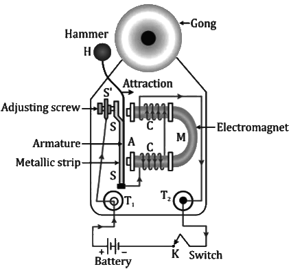
- The working of an electric bell is based on the magnetic effect of current. When the electric circuit is closed by pressing the switch K, the current flows through the coil CC and the core of the electromagnet gets magnetised. The electromagnet therefore attracts the armature A. Due to movement of the armature A, the hammer H strikes the gong G and the bell rings.
Force on a Current-carrying Conductor in a Magnetic Field
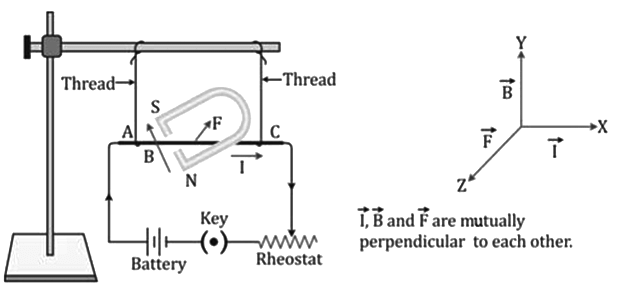
- When no current flows in the conductor, no force acts on the conductor and the conductor does not move. The wire is vertically below the support.
- When current is passed in the conductor, a force acts on the conductor in a direction perpendicular to both the direction of the current and the direction of the magnetic field.
- When the direction of the current through the conductor is reversed, the direction of force is also reversed.
- On reversing the direction of the magnetic field, the direction of force is reversed.
- When a conductor is placed such that the current in it is in the direction parallel to the direction of the magnetic field, no force acts on the conductor and it does not move.
Magnitude of force
- The magnitude of force acting on a current-carrying conductor placed in a magnetic field is found experimentally to depend on the following three factors:
i. The force is directly proportional to the current I flowing in the conductor, i.e. F ∝ I.
ii. The force is directly proportional to the strength of the magnetic field B, i.e. F ∝ B.
iii. The force is directly proportional to the length l of the conductor, i.e. F ∝ l.
F = IBl - The unit of magnetic field is given from the above equation as N A−1 m−1 .
Direction of force: The direction of force on a current-carrying conductor placed in a magnetic field is obtained by the Fleming's left-hand rule.
Fleming's left-hand rule: Stretch the forefinger, middle finger and thumb of your left hand mutually perpendicular to each other. If the forefinger indicates the direction of the magnetic field and the middle finger indicates the direction of the current, then the thumb will indicate the direction of motion of the conductor.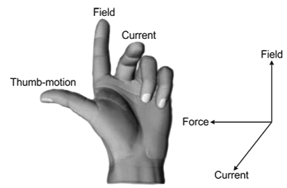
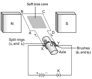
Simple DC Motor
- An electric motor is a device which converts electrical energy into mechanical energy.
- Principle: A DC motor works on the principle that when an electric current is passed through a conductor placed normally in a magnetic field, a force acts on the conductor as a result of which the conductor begins to move and mechanical energy (or work) is obtained. The direction of force is obtained by Fleming's left-hand rule.
Ways of increasing the speed of rotation of a coil: The speed of rotation of a coil can be increased by
i. Increasing the strength of the current in the coil
ii. Increasing the number of turns in the coil
iii. Increasing the area of the coil
iv. Increasing the strength of the magnetic field
Electromagnetic Induction
- Whenever there is a change in the number of magnetic field lines associated with a conductor, an electromotive force (emf) is developed between the ends of the conductor which lasts as long as the change is taking place. This phenomenon is called electromagnetic induction.
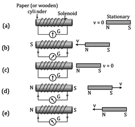
Conclusion
- A current flows in the coil only when there is a relative motion between the coil and the magnet due to which the galvanometer connected with the coil shows deflection.
- The direction of deflection in a galvanometer is reversed if the direction of motion (or polarity of the magnet) is reversed.
- The current in the coil is increased
i. By the rapid motion of the magnet (or coil)
ii. By using a strong magnet
iii. By increasing the area and the number of turns in the coil
Faraday’s Laws of Electromagnetic Induction
i. Whenever there is a change in the magnetic flux linked with a coil, an emf is induced. The induced emf lasts as long as there is a change in the magnetic flux linked with the coil.
ii. The magnitude of the emf induced is directly proportional to the rate of change of the magnetic flux linked with the coil. When the rate of change of the magnetic flux remains uniform, a steady emf is induced.
Factors Affecting the Magnitude of Induced EMF
The magnitude of induced emf is equal to the rate of change of magnetic flux, i.e.
Induced e.m.f. = (Change in magnetic flux/Time in which the magnetic flux changes)
Thus, for a given coil and magnet, emf depends on the following two factors:
(i) Change in the magnetic flux
(ii) Time in which the magnetic flux changes
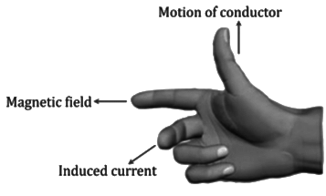
Direction of Induced EMF
The direction of induced emf (and hence the direction of induced current) can be obtained by any of the following two rules:
- Fleming's right-hand rule: Stretch the thumb, middle finger and forefinger of your right hand mutually perpendicular to each other. If the forefinger indicates the direction of the magnetic field and the thumb indicates the direction of the motion of the conductor, then the middle finger will indicate the direction of the induced current.
- Lenz's law: The direction of induced emf (or induced current) always tends to oppose the cause which produces it.
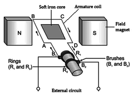
AC Generator
- An AC generator is a device which converts mechanical energy into electrical energy using the principle of electromagnetic induction.
- In a generator, a coil is rotated in a magnetic field. Due to rotation, the magnetic flux linked with the coil changes and therefore an emf is induced between the ends of the coil. Thus, a generator acts like a source of current if an external circuit containing a load is connected between the ends of its coil.
- The figure below represents the emf induced between the ends of the coil with respect to the position of the coil in the magnetic field when seen along the axis of rotation from the position of slip rings.
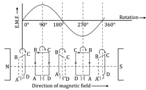
Frequency of Alternating Current
- In one complete rotation of the coil, we get one cycle of alternating emf in the external circuit.
- The alternating emf thus produced has a frequency which is equal to the frequency of rotation of the coil.
- If the coil makes n rotations per second, then the magnitude of induced emf is given as
e = e0 sin2πnt
and the current is expressed as
i = i0 sin2πnt
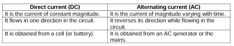
AC and DC
A current of constant magnitude and unique direction is called DC, while a current of changing magnitude and direction is called AC. A battery is a DC source, while an AC generator and the mains are AC sources.
Differences between AC and DC
Advantages of AC over DC
- The use of AC is advantageous over DC because the voltage of AC can be stepped up by using a step-up transformer at the power generating station before transmitting it over long distances. This reduces the loss of electrical energy as heat in the transmission line wires.
- The AC is then stepped down to 220 volt by using step-down transformers at the successive substations before supplying it to the houses or factories.
- If DC is generated at the power generating station, then its voltage cannot be increased for transmission. Due to the passage of high current in the transmission line wires, there will be a huge loss of electrical energy as heat in the line wires.
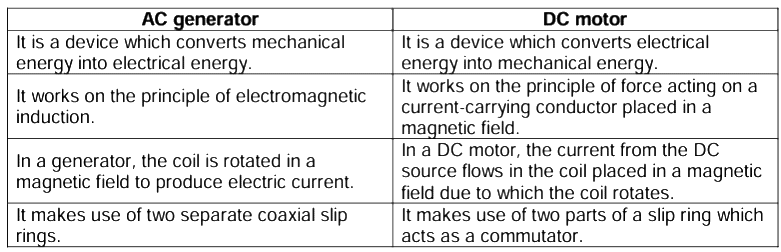
Distinction between an AC Generator and DC Motor
Transformer
- A transformer is a device by which the amplitude of an alternating emf can be increased or decreased.
- A transformer does not affect the frequency of the alternating voltage. The frequency remains unchanged (= 50 Hz).
- A transformer works on the principle of electromagnetic induction and makes use of two coils. When there is a change of magnetic field lines due to varying current in one coil, an induced varying current of the same frequency flows in the other coil.
- A transformer cannot be used with a direct current (DC) source.
- The ratio of number of turns Ns in the secondary coil to the number of turns Np in the primary coil (i.e. Ns/Np) is called the turns ratio.
Turns ratio = (Number of turns in secondary coil Ns/Number of turns in primary coil Np) - The advantage of using a closed core is that it gives a closed path for the magnetic field lines and therefore almost all the magnetic field lines caused by the current in the primary coil remain linked with the secondary coil.
- When the terminals of the primary coil are connected to the source of alternating emf, a varying current flows through the primary coil. This varying current produces a varying magnetic field in the core of the transformer. Thus, the magnetic field lines linked with the secondary coil vary.
- The change of magnetic field lines through the secondary coil induces an emf in it. The induced emf varies in the same manner as the applied emf in the primary coil varies and thus has the same frequency as that of the applied emf.
For a transformer, we have


For an ideal transformer, when there is no energy loss, the output power will be equal to the input power, that is
EsIs = EpIp
Types of Transformers
The two types of transformers are the step-up transformer and the step-down transformer.
- Step-up transformer: The transformer used to change a low voltage alternating emf to a high voltage alternating emf (of same frequency) is called a step-up transformer. In a step-up transformer, the number of turns in the secondary coil is more than the number of turns in the primary coil.
- Step-down transformer: The transformer used to change a high voltage alternating emf to a low voltage alternating emf (of same frequency) is called a step-down transformer. In a step-down transformer, the number of turns in the secondary coil is less than the number of turns in the primary coil.
|
28 videos|121 docs|14 tests
|
FAQs on Revision Notes: Electromagnetism - Physics Class 10 ICSE
| 1. What is Oersted’s experiment and what does it demonstrate about the relationship between electric current and magnetism? |  |
| 2. How can one determine the direction of the magnetic field created by a straight current-carrying conductor? | |
| 3. What is the magnetic field produced by a current in a loop, and how does it differ from that of a straight conductor? | |
| 4. What is a solenoid, and how does it generate a magnetic field? | |
| 5. What are some applications of electromagnets in everyday life? | |


mock tests for examination
,Revision Notes: Electromagnetism | Physics Class 10 ICSE
,Objective type Questions
,Summary
,Important questions
,ppt
,Previous Year Questions with Solutions
,shortcuts and tricks
,Semester Notes
,Free
,Revision Notes: Electromagnetism | Physics Class 10 ICSE
,Revision Notes: Electromagnetism | Physics Class 10 ICSE
,video lectures
,Sample Paper
,Exam
,MCQs
,Extra Questions
,Viva Questions
,practice quizzes
,study material
,past year papers
,


Revision Notes: Electromagnetism Free PDF Download
Importance of Revision Notes: Electromagnetism
Revision Notes: Electromagnetism
Revision Notes: Electromagnetism Class 10 Questions
Study Revision Notes: Electromagnetism on the App
|
© EduRev
|
Education Revolution
|


|


