Electricity and Magnetism Chapter Notes | Basic Technology for JSS 2 PDF Download

Introduction
Magnets play a key role in both nature and technology. In this chapter, you'll explore the laws of magnetism, the difference between natural and artificial magnets, and how magnets attract or repel. You'll also learn how to make and test a magnet, understand electromagnets and their uses, and see how electricity and magnetism are connected through Oersted’s experiment. Finally, the chapter explains electric circuits, how they work, and the materials that conduct electricity.

Laws of Magnetism and Test for a Magnet
Natural and Artificial Magnets
- A natural magnet occurs in nature and is not made by humans. An example of a natural magnet is magnetite, which is an ore of iron.
- On the other hand, an artificial magnet is created by humans and exhibits similar properties to a natural magnet.
- Artificial magnets are typically made from materials such as iron, steel, cobalt, or nickel.
Poles of a Magnet
- The poles of a magnet refer to the ends of a bar magnet where the magnetic force is strongest.
- The pole that faces geographic north is called the North Pole, while the pole that points towards geographic south is known as the South Pole.
Alignment of a Freely Suspended Magnet
- A magnet that is allowed to move freely will always align itself in the north-south direction.
- The north pole of the magnet points towards the geographic north, while the south pole points towards the geographic south.
- Sailors in the past used lodestones, a type of naturally magnetised rock, to help them find their way and determine directions.
Attraction and Repulsion Between the Magnets
- When the north pole of a bar magnet is brought close to the north pole of a freely suspended magnetic needle, the north pole of the needle moves away, indicating repulsion.
- Similarly, when the south pole of a bar magnet is brought near the south pole of a freely suspended magnetic needle, the south pole of the needle also moves away, showing repulsion.
- On the other hand, when the north pole of a bar magnet is brought close to the south pole of a freely suspended magnetic needle, the south pole of the needle is attracted and moves closer, indicating attraction.
- Likewise, when the south pole of a bar magnet is brought near the north pole of a freely suspended magnetic needle, the north pole of the needle is attracted and moves closer, demonstrating attraction.
- Like poles of magnets, such as north-north or south-south, repel each other.
- In contrast, opposite poles of magnets, like north-south or south-north, attract each other.
- When an unmagnetized bar of iron is brought near any pole of a magnetic needle, the needle is attracted to the iron bar.
- A magnet attracts a magnetic needle, but its opposite pole repels the same pole of the needle.
- An iron bar attracts both ends of a magnetic needle when it is near a magnet because the bar gets magnetised in the presence of the magnet.
Magnetic Compass
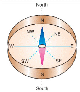
- A magnetic compass is a tool used by pilots and sailors to find directions like north, south, east, and west.
- It has a flat, round aluminium box at the bottom, which is marked with directions such as north, south, east, west, north-east, and north-west.
- Inside the box, there is a sharp needle that can move freely in any direction.
- On top of the box, there is a circular glass plate that protects the needle.
- By looking at the north-seeking end of the needle, we can determine the direction.
Make Your Own Magnet
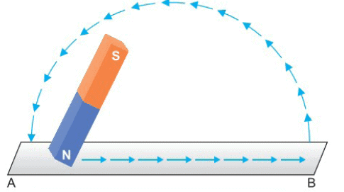
- Touch Method: A simple way to create a magnet is by using the "single touch method."
- Materials Needed: Start with a flat piece of iron (AB) and a permanent bar magnet.
- Step 1: Place the north pole of the bar magnet at point A on the iron piece.
- Step 2: Rub the magnet over the iron from A to B without lifting it off.
- Step 3: Repeat this rubbing motion 30 to 40 times.
- Testing the Magnetism: After rubbing, check the iron piece with a freely suspended magnetic needle. If the north pole of the needle is pushed away, the iron may become a magnet.
- Another Test: See if the iron piece can hold common pins or iron filings at its ends.
- Creating Magnets from Other Items: You can also create a magnet using an iron pin, a steel blade, or a sewing needle by rubbing it with a magnet in the same way.
Precautions in Using Magnets
- Magnets can lose their ability to attract or repel if they are heated too much or handled roughly.
- Magnets also lose their magnetism if they are not stored properly.
- Soft iron pieces should be kept in pairs in a wooden box, with their opposite ends facing each other and separated by a wooden piece.
- To prevent the loss of magnetism, soft iron pieces should be placed at both ends of the magnets.
- For a horseshoe magnet, a soft piece of iron should be placed across its ends to maintain its magnetism.
- Electronic devices such as computers, TVs, MP3 players, music systems, compact discs, audiotapes, cell phones, and transistors are very sensitive to magnets.
- Magnets should be kept away from these electronic devices because they can demagnetise them, potentially causing damage.
- A magnet attracts magnetic substances such as iron, steel, cobalt, and nickel towards itself.
- When a magnet is suspended freely, it points in the north-south direction.
- Similar poles of magnets (north-north or south-south) repel each other.
- Repulsion is a sure test of magnetism; if two objects repel each other, they are definitely magnets.
- When a bar magnet is rubbed over an unmagnetized piece of iron or steel, the iron or steel becomes a magnet.
- If a magnet is heated or handled roughly, it loses its magnetism.
Laws of Magnetism
- A magnet attracts magnetic substances like iron, steel, cobalt, and nickel towards itself.
- When suspended freely, a magnet points in the north-south direction.
- Similar poles of magnets (north-north or south-south) repel each other.
- Opposite poles of magnets (north-south or south-north) attract each other.
- Repulsion is the surest test of magnetism (if two objects repel, they are definitely magnets).
- When a bar magnet is rubbed over an unmagnetised piece of iron or steel, the iron or steel becomes a magnet.
- If a magnet is heated or handled roughly, it loses its magnetism.
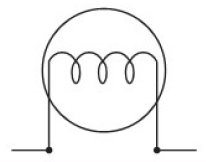
Electromagnets
- A solenoid with an iron core inside it is called an electromagnet.
- An electromagnet is a temporary magnet because it only works when electricity flows through it.
- The strength of an electromagnet increases when more electric current flows through it or when the number of turns in the coil increases.
Practical Uses of Electromagnets
- Electric Bells: Used to ring bells in various devices.
- Electric Fans: Employed in the operation of electric fans.
- Electric Motors: Integral to the functioning of electric motors.
- Electric Generators: Used in generators that require a strong magnetic field.
- Televisions: Control the electron beam in the picture tube of televisions.
- Magnetic Separation: Used in the magnetic separation of materials.
- Permanent Magnets: Help in creating strong permanent magnets.
- Medical Imaging: Used in various medical imaging techniques and devices.
Role of Electromagnets: Electromagnets are essential in generating magnetic fields when an electric current is applied. Their temporary nature allows for flexible use in technology and medicine, making them crucial components in many devices we rely on today.
Temporary and Permanent Magnets
- Temporary magnets are those that lose their magnetism once the source of their magnetism is removed. Examples of temporary magnets include electromagnets and magnets made from soft iron.
- Permanent magnets, on the other hand, retain their magnetism even after the source is taken away. Common materials for permanent magnets include steel and Alnico, an alloy of aluminium, nickel, and cobalt.
Electromagnetism and Its Effects
- In the past, before the 18th century, people believed that electricity and magnetism were entirely different and unrelated phenomena.
- However, subsequent discoveries revealed the intrinsic connection between electricity and magnetism, giving rise to the field of study known as electromagnetism.
Oersted’s Experiment to Show the Magnetic Effect of Current
- Setup: The magnetic needle is placed on a stand, allowing it to move freely. A circuit is created using a dry cell, a switch (K), and a variable resistor connected to a thick copper wire (AB).
- Initial Position: The wire AB is positioned above the magnetic needle, running parallel to it, with the current flowing from north to south.
- Observation 1: When the current is turned on, the north pole of the magnetic needle shifts towards the west. Increasing the current causes the needle to move further west.
- Observation 2: When the current is stopped, the needle returns to its original position.
- Observation 3: If the wire is positioned below the needle with current flowing from north to south, the north pole of the needle points towards the east.
- Observation 4: If the current flows from north to south above the magnetic needle, the north pole of the needle points to the east. If the current flows from north to south below the magnetic needle, the north pole points to the west.
Conclusions Drawn from Oersted’s Experiment
- Whenever an electric current passes through a straight conductor (wire), it behaves like a magnet.
- The strength of the magnetic effect increases when the current increases.
- The magnetic field is set up at a right angle to the direction of the current flow.
- The direction in which the north pole of the magnetic needle moves depends on: (a) the direction of the current in the conductor, and (b) whether the conductor is above or below the needle.
The Electric Bell
- An electric bell is a device that functions using an electromagnet and electrical power.
- It is made up of several components mounted on a flat board, typically made of wood or plastic.
Parts of an Electric Bell
- Electromagnet: The electromagnet is a crucial part of the electric bell. It consists of a U-shaped soft iron rod with insulated copper wire coils wrapped around each arm. The coils create a magnetic field when electricity flows through them. One end of the wire is connected to terminal T1, and the other end is connected to terminal T2.
- Armature: The armature is a soft iron bar that is suspended from a stud (S) using a flat spring. This allows the armature to move freely and align with the poles of the electromagnet when it is energised.
- Contact Spring: The contact spring is a flat steel spring that is slightly bent. It is attached to the armature with screws, and its other end is connected to a silver contact point. The contact point is designed to withstand damage from sparking when the circuit is completed.
- Contact Screw Adjustment: This component consists of a brass pillar and a brass screw made from a silver-cadmium alloy to prevent sparking. The screw goes through the pillar and is linked to terminal T2 and a copper wire.
- Hammer and Gong: The hammer is made of steel and is attached to the armature. When the armature moves, the hammer strikes the gong, which is made of brass. The gong is positioned so that the hammer can hit it, producing sound.
Working of an Electric Bell
- The terminals T1 and T2 of the bell are connected to a battery through a push-button switch.
- When the push button is pressed, the electric current flows from the dry cell to the electromagnet, then to the contact screw, and back to the dry cell.
- The electromagnet gets activated and pulls the soft iron armature strongly towards itself.
- The spring connecting the armature and stud S gets under tension.
- The hammer attached to the armature strikes the gong and produces sound.
- The electric circuit breaks at the contact point when the armature moves, so the electromagnet loses its magnetism.
- The armature and hammer move back to their original position due to the spring’s tension.
- When the armature returns, the circuit is completed again, and the electromagnet pulls the armature again.
- This process repeats rapidly, making the hammer hit the gong again and again, producing the familiar ringing sound of the bell.
Electric Circuit and Its Components
Electricity and magnetism are exciting topics in science that help us understand how things like lights, fans, and magnets work. Electricity is the flow of tiny particles called electrons that give power to gadgets and machines. Magnetism is the force that makes magnets stick to some metals or push them away. In this chapter, we will learn how electric circuits work, what their parts are, how to connect them, and how magnets behave. We will also explore how electricity and magnetism are connected and why they are so important in our daily lives.
Quantity of Electric Charge
- Electric charge is the measure of charge that moves from a region of higher potential to a region of lower potential within a conductor.
- The total charge that flows through a conductor is referred to as electric charge.
- We denote the quantity of electricity with the symbol Q.
- The standard unit for electric charge is the coulomb, which is commonly abbreviated as C.
- One coulomb is defined as the amount of charge that passes through a conductor when a current of one ampere flows for one second.
- The charge of a single electron is approximately 1.6 × 10⁻¹⁹ C.
- Therefore, the charge on one electron is about 1.6 × 10⁻¹⁹ C.
Electricity as a Flow of Charges
- Electricity refers to the movement of electric charge, which is measured in coulombs. This movement is what we call an electric current.
- Electric current (I) indicates the speed at which charge flows through a conductor in one second.
- The formula for electric current is I = Q / t, where I represents the current, Q is the charge, and t is the time.
- The unit for electric current is known as an ampere, abbreviated as A.
- Definition of one ampere: One ampere is defined as the current that occurs when one coulomb of charge flows through a conductor in one second. In other words, 1 ampere = 1 coulomb / 1 second.
Bigger units of current
- 1 kiloampere (kA) = 103 A = 1,000 A.
- 1 Megaampere (MA) = 106 A = 1,000,000 A.
Smaller units of current
- 1 milliampere (mA) = 10-3 A = 0.001 A.
- 1 microampere (µA) = 10-6 A = 0.000001 A.
Relationship Between Current, Number of Electrons, and Time
- Electric current refers to the movement of electric charge within a circuit, which is necessary for powering electrical devices.
- The current can be calculated using the formula I = Q / t, where I is the current, Q is the charge, and t is the time.
- If n electrons pass through a circuit, and each electron has a charge of e, the total charge Q can be calculated as Q = n × e.
- Substituting this into the current formula gives I = (n × e) / t.
Electric Cell as a Source of Electricity
- A cell is a small device that produces an electric current.
- Cells are used in torches, transistors, radios, bicycle lamps, small tape recorders, and more.
- Button cells (very small cells) are used in calculators, wrist watches, and other small devices, and these are called primary cells.
- Cells that can be recharged are called secondary cells.
- Secondary cells are used in cars, trucks, tractors, motorcycles, and other vehicles to power headlights and engines.
Electrical Resistance or Resistor
- An electric bulb contains a thin, coiled wire made of tungsten, which is connected to two brass terminals.
- When the bulb is connected to a dry cell using copper wires, it starts to glow.
- The tungsten wire, being thin, resists the flow of electric current, causing it to become white-hot and emit light. In contrast, the brass terminals and copper wires do not shine because they have lower resistance.
- Resistance is the term used to describe how much a material hinders the flow of electric current. It measures the opposition a material offers to electric current and is quantified in ohms (Ω).
- One ohm of resistance is defined as the situation where 1 ampere of current flows with a voltage of 1 volt across a conductor. This relationship is expressed as 1 Ω = 1 V / 1 A.
- The formula for calculating resistance is R = V / I, where R is resistance, V is potential difference, and I is current flowing through it.
- For example, if a current of 2 A flows through a conductor with a potential difference of 4 V, then the resistance of the conductor is R = V / I = 4 V / 2 A = 2 Ω.
- Alternatively, one ohm resistance can be defined as: A conductor is said to have one ohm resistance if the ratio of potential difference at its ends and the current flowing through it is 1.
For example, in the following situations, the resistance of a conductor is one ohm:
- Current of 0.5 A flowing through a conductor at a potential difference of 0.5 V: R = V / I = 0.5 V / 0.5 A = 1 Ω.
- Current of 10 A flowing through a conductor at a potential difference of 10 V: R = V / I = 10 V / 10 A = 1 Ω.
- In both cases, the ratio of V / I is 1, so the resistance is one ohm.
Simple Electric Circuit – Series
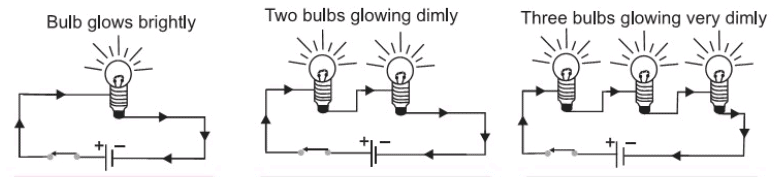
- The figure shows a single bulb connected to a dry cell through a switch.
- When the circuit is closed, the bulb glows brightly.
- The figure shows two bulbs connected to a dry cell, such that the positive of one bulb is connected to the negative of the other bulb.
- When the circuit is closed, the two bulbs glow dimly.
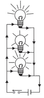
- The figure shows three bulbs connected to a dry cell, such that the positive of one bulb is connected to the negative of the other bulb.
- When the circuit is closed, the three bulbs glow, but very dimly.
- When resistors (like bulbs) are connected in an electric circuit in such a way that the positive of one resistor acts as the negative of the other, then the resistors (bulbs) are said to be connected in series.
Characteristics of a Series Circuit
- The sum total of resistances in series increases with the increase in the number of resistors.
- The potential difference remains constant, but the current in the series circuit decreases with the increase in the number of resistors.
- All elements (bulbs) in a series circuit work simultaneously; if the circuit is broken anywhere between the elements (bulbs), none of the elements function.
Simple Electric Circuit – Parallel
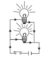
- The figure shows two bulbs connected to a cell through a switch, such that the positive end of the cell is simultaneously connected to one point of the bulbs and the negative end of the cell is simultaneously connected to the other point of the bulbs.
- The figure shows a similar circuit, except there are three bulbs.
- It is observed that when the circuit is closed, all the bulbs glow with the same brightness.
- Furthermore, if the circuit is broken for a particular bulb, the other bulbs continue functioning independently.
- When resistors (bulbs) are connected in an electric circuit such that all of them are connected to the common positive and common negative terminals of a cell, then the resistors (bulbs) are said to be connected in parallel.
Characteristics of a Parallel Circuit
- In a parallel circuit, the total resistance decreases when more resistors are added.
- The current passing through each resistor is inversely related to its resistance, meaning that a higher resistance leads to less current.
- Each resistor in a parallel circuit functions independently of the others.
Symbolic Representation of Electrical Components
- Conducting wire: The conducting wire is represented by a straight line. It is usually made of copper and is provided with cotton insulation, and the resistance of the wire is negligible.

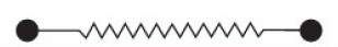
- Resistor: A fixed resistance wire or a resistor is represented by a zigzag line. The two thick dots are the brass terminals between which the resistance wire is stretched. The resistance wire is generally made from metallic alloys such as nichrome, Eureka, constantan, manganin, tungsten, etc.
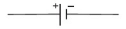
- Cell: A cell is represented by a thin, long line for the positive terminal and a thick, short line for the negative terminal, as shown in Figure
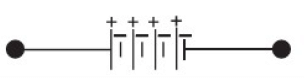
- Battery: A combination of two or more cells is called a battery. The figure shows a battery of three cells in series.
 The figure shows a battery of three cells in parallel.
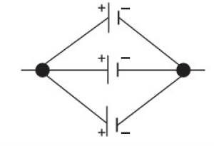
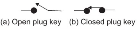
- Key: A plug key or a single key is an electric switch. Figure (a) shows an open plug key when no current does flows in the electric circuit. Figure (b) shows a closed plug key when current flows in the electric circuit.
- Bulb: A bulb is represented by two small parallel lines which are connected by a zigzag line, as shown in the figure.
Good and Bad Conductors
- Refer to Figure: If the cell is connected to the bulb by brass or aluminium wires, the bulb glows because brass and aluminium allow the electric current to flow through them.
- Materials that allow electric current to flow through them are called good conductors.
- Examples of good conductors: Silver, copper, aluminium, gold, iron, brass, tin, steel, lead, impure water, human body, animals, living plants, etc.
- Connect the cell to the bulb by cotton thread or rubber bands instead of copper wires; you will observe that the bulb does not glow.
- It is because cotton or rubber wires do not allow the electric current to flow through them; they are bad conductors.
- Examples of bad conductors: Plastic, nylon, bakelite, wood, cork, rubber, cotton, polythene, glass, ebonite, flax, pure water, leather, etc.
Points to Remember
- The electric current flows through a circuit only if the circuit is closed or complete.
- Every part of the circuit must be a conductor.
- If any of the above conditions are not satisfied, the electric current stops flowing.
- Materials that do not allow the electric current to flow through them are called bad conductors or insulators.
FAQs on Electricity and Magnetism Chapter Notes - Basic Technology for JSS 2
| 1. What are the basic laws of magnetism? |  |
| 2. What is an electric circuit and its main components? | |
| 3. How is electric current related to the flow of electrons in a circuit? | |
| 4. What is electrical resistance and what role does a resistor play in a circuit? | |
| 5. What is a simple electric circuit in series and how does it work? | |


Previous Year Questions with Solutions
,Electricity and Magnetism Chapter Notes | Basic Technology for JSS 2
,shortcuts and tricks
,mock tests for examination
,Electricity and Magnetism Chapter Notes | Basic Technology for JSS 2
,past year papers
,ppt
,Semester Notes
,MCQs
,Sample Paper
,Electricity and Magnetism Chapter Notes | Basic Technology for JSS 2
,Important questions
,Exam
,practice quizzes
,Free
,Objective type Questions
,Extra Questions
,Summary
,study material
,Viva Questions
,video lectures
;


Chapter Notes: Electricity and Magnetism Free PDF Download
Importance of Chapter Notes: Electricity and Magnetism
Chapter Notes: Electricity and Magnetism
Chapter Notes: Electricity and Magnetism JSS 2 Questions
Study Chapter Notes: Electricity and Magnetism on the App
|
© EduRev
|
Education Revolution
|


|


