CURRENT ELECTRICITY, Chapter Notes, Class 12, Physics, (IIT-JEE & AIPMT)

Electric Current, Ohm's Law and Drift of Electrons - Current Electricity, Class 12, Physics
1. Introduction
- Conductor
In some materials, the outer electrons of each atoms or molecules are only weakly bound to it. These electrons are almost free to move throughout the body of the material and are called free electrons. They are also known as conduction electrons. When such a material is placed in an electric field, the free electrons move in a direction opposite to the field. Such materials are called conductors.
- Insulator :
Another class of materials is called insulators in which all the electrons are tightly bound to their respective atoms or molecules. Effectively, there are no free electrons. When such a material is placed in an electric field, the electrons may slightly shift opposite to the field but they can't leave their parent atoms or molecules and hence can't move through long distances. Such materials are also called dielectrics.
- Semiconductor :
In semiconductors, the behaviour is like an insulator at low levels of temperature. But at higher temperatures, a small number of electrons are able to free themselves and they respond to the applied electric field. As the number of free electrons in a semiconductor is much smaller then that in a conductor, its behaviour is in between a conductor and an insulator and hence, the name semiconductor. A freed electron in a semiconductor leaves a vacancy in its normal bound position. These vacancies also help in conduction.
2. Electric Current and Current Density
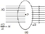
When there is a transfer of charge from one side of an area to the other, we say that there is an electric current through the area. If the moving charges are positive, the current is in the direction of motion, if they are negative, the current is opposite to the direction of motion. If a charge ΔQ crosses an area in time Δt, we define the average electric current through the area during this time as

The current at time t is

Thus, electric current through an area is the rate of transfer of charge from one side of the area to the other. The SI unit of current is ampere. If one coulomb of charge crosses an area in one second, the current is one ampere. It is one of the seven base units accepted in SI.
Ex.1 If q = 2t2 3, find current at t = 2 sec ?
Sol. 
i = 4t
 i at 2 sec = 4 × 2 = 8 A
We shall now define a vector quantity known as electric current density at a point. To define the current density at a point P, we draw a small area DS through P perpendicular to the flow of charges(shown in figure) If Di be the current through the area DS, the average current density is

The current density at the point P is

The direction of the current density is the same as the direction of the current. Thus, it is along the motion of the moving charges, if the charges are positive and opposite to the motion of the charges, if the charges are negative. If a current i is uniformly distributed over an area S and is perpendicular to it,

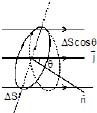
Now let us consider an area DS which is not necessarily perpendicular to the current (figure shown) If the normal to the area makes an angle q with the direction of the current, the current density is,

or, Δi = j ΔS cos q
where Δi is the current through ΔS, If  be the area vector corresponding to the area ΔS, we have
For a finite area,
Note carefully that an electric current has direction as well as magnitude but it is not a vector quantity. It does not add like vectors. Therefore current is neither a vector quantity nor a scalar quantity but a tensor quantity. The current density is a vector quantity.
Ex.2 An electron beam has an aperature 1.0 mm2. A total of 6.0 × 10¹⁰electrons go through any perpendicular cross-section per second. Find (a) the current and (b) the current density in the beam.
Sol. The total charge crossing a perpendicular cross-section in one second is
q = ne
= 6.0 × 1016 × 1.6 × 10-19 C
= 9.6 × 10⁻³ C
The current is
 =
=  = 9.6 × 10⁻³ A
As the charge is negative, the current is opposite to be direction of motion of the beam.
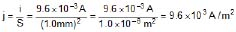
(b) The current density is
3. Drift Speed
A conductor contains a large number of loosely bound electrons which we call free electrons or conduction electrons. The remaining material is a collection of relatively heavy positive ions which we call lattice. These ions keep on vibrating about their mean positions. The average amplitude depends on the temperature. Occasionally, a free electron collides or interacts in some other fashion with the lattice. The speed and direction of the electron changes randomly at each such event. As a result, the electron moves in a zig-zag path. As there is a large number of free electrons moving in random directions, the number of electrons crossing an area DS from one side very nearly equals the number crossing from the other side in any given time interval. The electric current through the area is, therefore, zero.
When there is an electric field inside the conductor, a force acts on each electron in the direction opposite to the field. The electrons get biased in their random motion in favour of the force. As a result, the electrons drift slowly in this direction. At each collision, the electron starts afresh in a random direction with a random speed but gains an additional velocity v' due to the electric field. This velocity v' increases with time and suddenly becomes zero as the electron makes a collision with the lattice and starts afresh with a random velocity. As. the time ,t between successive collisions is small, the electron "slowly and steadily drifts opposite to the applied field (shown figure). If the electron drifts a distance l in a long time t, we define drift speed as

If t be the average time between successive collisions, the distance drifted during this period is
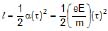
The drift speed is 
It is proportional to the electric field E and to the average collision-time t.
The random motion of free electrons does not contribute to the drift of these electrons. Also, the average collision-time is constant for a given material at a given temperature. We, therefore, make the following assumption for our present purpose of discussing electric current.
When no electric field exists in a conductor, the free electrons stay at rest (Vd = 0) and when a field E exists, they move with a constant velocity
 ...(1)
opposite to the field. The constant k depends on the material of the conductor and its temperature.
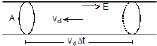
Let us now find the relation between the current density and the drift speed. Consider a cylindrical conductor of cross-sectional area A in which an electric field E exists. Consider a length vd Δt of the conductor (figure shown). The volume of this portion is AvdΔt. If there are n free electrons per unit volume of the wire, the number of free electrons in this portion is nAvdΔt. All these electrons cross the area A in time Δt. Thus, the charge crossing this area in time Δt is
ΔQ = nAvd Δt e
or,  = nAvde
and j =  ...(2)
Ex.3 Calculate the drift speed of the electrons when 1 A of current exists in a copper wire of cross-section 2 mm2. The number of free electrons in 1 cm3 of copper is 8.5 × 10²².
Sol. We have
j = nevd
or,  =
= 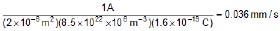
We see that the drift speed is indeed small.
4. OHM'S LAW
Using equations (1) and (2)

or,  ...(3)
where s = 
where s depends only on material of the conductor and its temperature. This constant is called the electrical conductivity of the material. Equation (3) is known as Ohm's law.
The resistivity of a material is defined as
 =
=  ...(4)
Ohm's law tells us that the conductivity (or resistivity) of a material is independent of the electric field existing in the material. This is valid for conductors over a wide range of field.
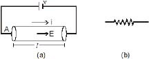
Suppose we have a conductor of length l and uniform cross-sectional area A (figure shown) Let us apply a potential difference V between the ends of the conductor. The electric field inside the conductor is  . If the current in the conductor is i, the current density is
  . Ohm's law j = sE then becomes

or,  ...(5)
or, V = R i ...(6)
R is called the resistance of the given conductor. The quantity  is called conductance.
Equation (5) is another form of Ohm's law which is widely used in circuit analysis. The unit of resistance is called ohm and is denoted by symbol W. An object of conducting material, having a resistance of desired value, is called a resistor.
From equation (5) and (6)
 ...(7)
From equation (7), the unit of resistivity ρ is ohm-metre, also written as ?-m. The unit of conductivity (σ) is (ohm-m) written as mho/m.
from eq. (4) & (7)
where r = resistivity
l = length along the direction of current
A = Area of the cross section perpendicular to direction of current
n = no. of free charges per unit volume.
τ = relaxation time
m = mass of electron
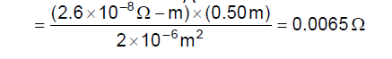
Ex.4 Calculate the resistance of an aluminium wire of length 50 cm and cross-sectional area 2.0 mm2. The resistivity of aluminium is ρ = 2.6 × 10⁻⁸ ?-m
Sol. The resistance is R = 
We arrived at Ohm's law by making several assumptions about the existence and behaviour of the free electrons. These assumption are not valid for semiconductors, insulators, solutions etc. Ohm's law cannot be applied in such cases.
Ex.5 The dimensions of a conductor of specific resistance r are shown below. Find the resistance of the conductor across AB, CD and EF.
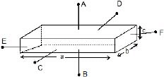
Sol. 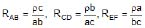
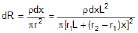
Ex.6 A portion of length L is cut out of a conical solid wire. The two ends of this portion have circular cross-sections of radii r1 and r2 (r2 > r1). It is connected lengthwise to a circuit and a current i is flowing in it. The resistivity of the material of the wire is ρ. Calculate the resistance of the considered portion and the voltage developed across it.
Sol. If follows from the figure, that
tanq = 
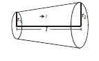
Therefore, r = r1 x tan q = r1 x  =
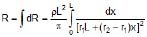
= 

Therefore, 
 ⇒
⇒ 
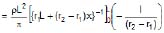
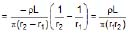 Therefore,
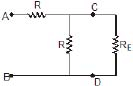
Ex.7 The space between two coaxial cylinders, whose radii are a and b (where a < b as in (figure shown) is filled with a conducting medium. The specific conductivity of the medium is σ.
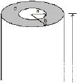
(a) Compute the resistance along the length of cylinder.
(b) Compute the resistance between the cylinders in the radial direction. Assume that the cylinders are very long as compared to their radii, i.e., L >> b, where L is the length of the cylinders.
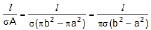
Sol. (a) R =  =
=
(b) From Ohm's law, we have

Assuming radial current density.  becomes
 for a < r < b
and, therefore, 
Here we have used the assumption that L >> b so that  and are in cylindrically symmetric form. The potential drop across the medium is thus :
 =
= 
The resistance

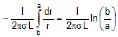
Method 2 : We split the medium into differential cylindrical shell elements of width dr, in series. The current flow is cylindrically symmetric (L >> b). The area through which the current flows across a shell of radius r is A(r) = 2πrL. The length the current flows, passing through a shell of radius r is dr. Therefore, the resistance of the shell of radius r is :

Since the shells are connected in a series, we have

===============================================================
Resisitivity and its Temperature Dependence - Current Electricity, Class 12, Physics
Effect of Temperature on Resistance
(a) Resistance of Pure Metals
(i) We know that 
For a given conductor, l, A and n are constant, hence R is directly proportional to (1/τ)
If λ represents the mean free path (Average distance covered between two successive collisions) of the electron and vrms, the root-mean-square speed, then
 Hence R is directly proportional to
Now,
(a) λ decreases with rise in temperature because the amplitude of vibrations of the +ve ions of the metal increases and they create more hindrance in the movement of electrons and,
(b) (i) vrms increases because vrms is directly proportional to under root T. Therefore, Resistance of the metallic wire increases with rise in temperature. As ρ is directly proportional to R and σ is directly proportional to (1/ρ), hence resistivity increases and conductivity decreases with rise in temperature of the metallic of the metallic wires.
(ii) If R0 and Rτ represent the resistances of metallic wire at 0°C and t°C respectively then Rt is given by the following formula :

where α is called as the Temperature coefficient of resistance of the material of the wire.
α depends on material and temperature but generally it is taken as a constant for a particular material for small change.
Rt - R0 = R0 α t
for very small change in temperature dR = R0 α dt
(c) Resistance of semiconductors
(i) There are certain substances whose conductivity lies in between that of insulators and conductors, higher than that of insulators but lower than that of conductors. These are called as semiconductors, e.g., silicon, germanium, carbon etc.
(ii) The resistivity of semiconductors decreases with increase in temperature i.e., a for semiconductors is -ve and high.
(iii) Though at ordinary temperature the value of n (no. of free electrons per unit volume) for these materials is very small as compared to metals, but increases very rapidly with rise in temperature (this happens due to breaking of covalent bonds). Though τ decreases but factor of n dominates. Therefore, the resistance
 goes on decreasing with increase in temperature.
5. Battery and EMF
A battery is a device which maintains a potential difference between its two terminals A and B. Figure shows a schematic diagram of a battery. Some internal mechanism exerts forces on the charges of the battery material. This force drives the positive charges of the battery material towards A and the negative charges of the battery material towards B. We show the force on a positive charge q as  . As positive charge accumulates on A and negative charge on B, a potential difference develops and grows between A and B. An electric field is developed in the battery material from A to B and exerts a force
  on a charge q. The direction of this force is opposite to that of
  In steady state, the charge accumulation on A and B is such that
  . No further accumulation takes place.
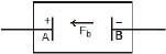
If a charge q is taken from the terminal B to the terminal A , the work done by the battery force Fb is
W = Fb d where d is the distance between A and B. The work done by the battery force per unit charge is

This quantity is called the emf of the battery. The full form of emf is electromotive force. The name is misleading in the sense that emf is not a force, it is work done/charge. We shall continue to denote this quantity by the short name emf. If nothing is connected externally between A and B,
Fb = Fe = qE
or, Fbd = qEd = qV
where V = Ed is the potential difference between the terminals. Thus,

Thus, the emf of a battery equals the potential difference between its terminals when the terminals are not connected externally.
Potential difference and emf are two different quantities whose magnitudes may be equal in certain conditions. The emf is the work done per unit charge by the battery force Fb which is non-electrostatic in nature. The potential difference originates from the electrostatic field created by the charges accumulated on the terminals of the battery.
A battery is often prepared by putting two rods or plates of different metals in a chemical solution. Such a battery, using chemical reactions to generate emf, is often called a cell.

Now suppose the terminals of a battery are connected by a conducting wire as shown in above figure. As the terminal A is at a higher potential than B, there is an electric field in the wire in the direction shown in the figure. The free electrons in the wire move in the opposite direction .and enter the battery at the terminal A. Some electrons are withdrawn from the terminal B which enter the wire through the right end. Thus, the potential difference between A and B tends to decrease. If this potential difference decreases, the electrostatic force Fe inside the battery also decreases. The force Fb due to the battery mechanism remains the same. Thus, there is a net force on the positive charges of the battery material from B to A. The positive charges rush towards A and neutralise the effect of the electrons coming at A from the wire. Similarly, the negative charges rush towards B. Thus, the potential difference between A and B is maintained.
For calculation of current, motion of a positive charge in one direction is equivalent to the motion of a negative charge in opposite direction. Using this fact, We can describe the above situation by a simpler model. The positive terminal of the battery supplies positive charges to the wire. These charges are pushed through the wire by the electric field and they reach the negative terminal of the battery. The battery mechanism drives these charges back to the positive terminal against the electric fIeld existing in the battery and the process continues. This maintains a steady current in the circuit
Current can also be driven into a battery in the reverse direction. In such a case, positive charge enters the battery at the positive terminal, moves inside the battery to the· negative terminal and leaves the battery from the negative terminal. Such a process is called charging of the battery. The more common process in which. the positive charge comes out of the battery from the positive terminal is called discharging of the battery.
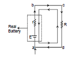
Ex.8 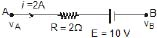
Find vA - vB
Sol. vA - iR - E = vB
vA - vB = iR E = 4 +10 = 14 volt
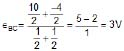
Ex.9 Shown in the figure. Find out the current in the wire BD
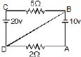
Sol. Let at point D potential = 0 and write the potential of other points then current in wire AD =  = 5A from A to D current in wire CB =
  = 4A from C to B. Therefore, current in wire BD = 1 A from D to B.
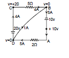
Ex.10 Find the current in each wire
Sol. Let potential at point A is 0 volt then potential of other points is shown in figure.
Current in BG =  = 40 A from G to B
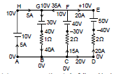
Current in FC =  = 15A from C to K
current in DE =  from D to E
current in wire AH = 40 - 35 = 5 A from A to H
6. Kirchhoff's Laws for Circuit Analysis
Before moving on to the statement of Kirchhoff's law, we state some conventions to be followed in circuit analysis :
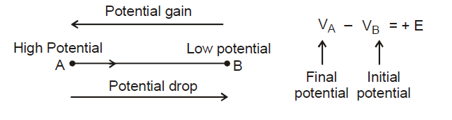
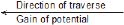
(1) Direction of conventional current is from high potential to low potential terminal.
(2) Current flows from high potential node A to low potential node B. if we traverse from point A to B, there is drop of potential; similarly from B to A, there is gain of potential.
If we traverse from point A to B, there is drop of potential; similarly from B to A, there is gain of potential. If a source of emf is traversed from negative to positive terminal, the change in potential is +E.
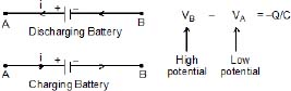
While discharging, current is drawn from the battery, the current comes out from positive terminal and enters negative terminal, while charging of battery current is forced from positive terminal of the battery to negative terminal. Irrespective of direction of current through a battery the sign convention mentioned above holds.
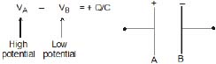
The positive plate of a capacitor is at high potential and negative plate at low potential. If we traverse a capacitor from positive plate to negative plate, the change in potential is -Q/C
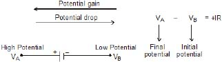
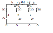
If we traverse a resistor in the direction of current, the change in potential is -IR.
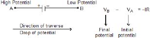
If we traverse a resistor in the direction opposite to the direction of current, the change in potential is +IR.
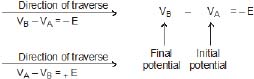
Positive terminal of source of emf is at high potential and negative terminal at low potential. If we traverse a source of emf from the positive terminal to negative terminal, the change in potential is -E.
If a capacitor is traversed from negative plate to positive plate, the change in potential is Q/C.
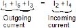
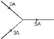
(a) The Kirchhoff's Current Law
The Kirchhoff's current law (KCL) states that the algebraic sum of the currents entering the junction must equal to sum of the
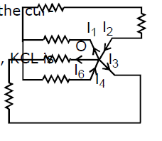
currents leaving the junction. From the standard point of physics, KCL is a statement of charge conservation.
The KCL applied to junction O yields.
Ex.11 Find the potential at point A
Sol. Let potential at A = x, applying kirchhoff current law at junction A
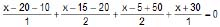
⇒ 
⇒ 6x 10 = 0
⇒ 
Potential at A = 
Ex.12
Find the current in every branch ?
Sol. Let we assume x potential at the top junction & zero potential at lower junction. As from KCL,net current on a junction is O
i1 i2 i3 = 0
3x = 35 ⇒ 
Therefore,  A
A
Similarly, i2 =  A ; i3 =
  A.
A.
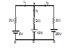
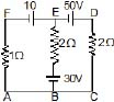
Ex.13
Find the current in every branch ?
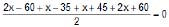
Sol. Assume x potential at the upper junction & zero potential at the lower junction.
By KCl, we know that net current on a junction is zero.
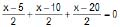
Therefore, i1 i2 i3 i4 = 0
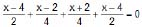
2x - 8 + x - 2 + x + 2 + 2x - 8 = 0 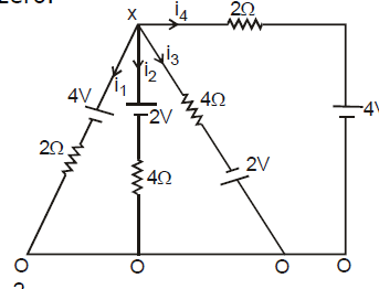
6x - 16 = 0 ⇒  V
V
Therefore,  A,
A,  A,
A,  A,
A,  A
A
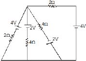
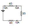
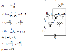
Ex.14
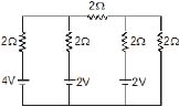
Find the current in every branch ?
Sol. The above question could be solved by assuming potential x & y at the top junctions & zero potential at lower junctions
At the junction 1 applying KCL,
i1 i2 i3 = 0
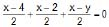
⇒ 3x - y = 6 ...(1)
At the junction 2 applying KCL,
i4 + i5 + i6 = 0

⇒ 3y - x = 2 ...(2)
Solving (1) & (2)
9x - 3y = 18 ⇒ 3y - x = 2
⇒ 8x = 20
x =  , y =
, y = 
Just put the values of x & y & then the evaluate the current in every branch
=================================================================
Kirchoff's Rules - Current Electricity, Class 12, Physics
(b) The Kirchhoff's Voltage Law
The Kirchhoff's voltage law (KVL) states that the algebraic sum of the potential difference around any closed loop of an electric circuit is zero. The KVL is a statement of conservation of energy. The KVL reflects that electric force is conservative, the work done by a conservative force on a charge taken around a closed path is zero.
 We can move clockwise or anticlockwise, it will make no difference because the overall sum of the potential difference is zero.
 We can start from any point on the loop, we just have to finish at the same point.
 An ideal battery is modelled by an independent voltage source of emf E and an internal resistance r as shown in figure A real battery always absorbs power when there is a current through it, thereby offering resistance to flow of current.
Applying KVL around the single loop in anticlockwise direction, starting from point A, we have
Hence, 
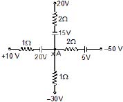
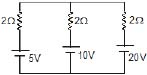
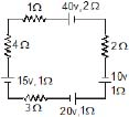
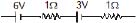
Ex.15 Find current in the circuit
Sol. Therefore, all the elements are connected in series
Therefore, current in all of them will be same
let current = I
Applying kirchhoff voltage law in ABCDA loop 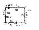
10 + 4i - 20 + i + 15 + 2i - 30 + 3i = 0
10 i = 25 ⇒ i = 2.5 A
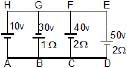
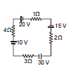
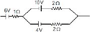
Ex.16 Find the current in each wire applying only kirchhoff voltage law
Sol. Applying kirchhoff voltage law in loop ABEFA
i1 + 30 + 2 (i1 + i2) - 10 = 0
3i1 + 2i2 + 20 = 0 ...(i)
Applying kirchhoff voltage law in BCDEB
+30 + 2(i1 + i2) + 50 + 2i2 = 0
4i2 + 2i1 + 80 = 0
2i2 + i1 + 40 = 0 ...(ii)
Solving (i) and (ii)
3[-40 -2i2] + 2i2 + 20 = 0 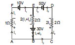
-120 - 4i2 + 20 = 0
i2 = - 25 A
and i1 = 10 A
Therefore, i1 i2 = - 15 A
current in wire AF = 10 A from A to E
current in wire EB = 15 A from B to E
current in wire DE = 25 A from D to C
=================================================================
Combination of Resistors:Series and Parallel - Current Electricity, Class 12, Physics
7. Combination of Resistance
A number of resistance can be connected in a circuit and any complicated combination can be, in general, reduced essentially to two different types, namely series and parallel combinations.
(a) Resistance in Series
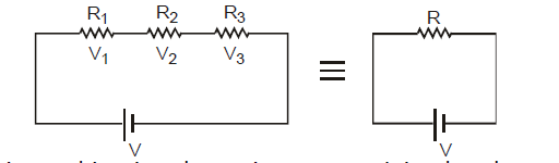
(i) In this combination the resistance are joined end to end. The second end of each resistance is joined to first end of the next resistance and so on. A cell is connected between the first end of first resistance and second end of last resistance. Figure shows three resistances R1, R2 and R3 connected in this way. Let V1, V2 and V3 are the potential differences across these resistances.
(ii) In this combination current flowing through each resistance will be same and will be equal to current supplied by the battery.
(iii) As resistances are different and current flowing through them is same, hence potential differences across them will be different. Applied potential difference will be distributed among three resistances directly in their ratio.
As i is constant, hence V is directly proportional to R
i.e., V1 = iR1, V2 = iR2, v3 = iR3
(iv) If the potential difference between the points A and D is V, then
(v) If the combination of resistances between two points is replaced by a single resistance R such that there is no change in the current of the circuit in the potential difference between those two points, then the single resistance R will be equivlaent to combination and V = i R i.e.,

(v) Thus in series combination of resistances, important conclusion are
(a) Equivalent Resistance > highest individual resistance
(b) Current supplied by source = Current in each resistance
or  =
=  =
=  =
= 
(c) The total potential difference V between points A and B is shared among the three resistances directly in their ratio
V1 : V2 : V3 = R1 : R2 : R3
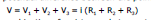
(b) Resistance in Parallel
(i) When two or more resistance are combined in such a way that their first ends are connected to one terminal of the battery while other ends are connected to other terminal, then they are said to be connected in parallel. Figure shows three resistances R1, R2 and R3 joined in parallel between two points A and B. Suppose the current flowing from the battery is i. This current gets divided into three parts at the junction A. Let the currents in three resistance R1 , R2 and R3, are i1, i2, i3respectively.
(ii) Suppose potential difference between points A and B is V. Because each resistance is connected between same two points A and B, hence potential difference across each resistance will be same and will be equal to applied potential difference V.
(iii) Since potential difference across each resistance is same, hence current approaching the junction A is divided among three resistances reciprocally in their ratio.
As V is constant, hence i µ (1/R) i.e.,


(iv) Because i the main current which is divided into three parts i1, i2 and i3 at the junction A.
hence, 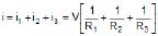
If the equivalent resistance between the points A and B is R, then i = 
Thus, 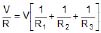 or
or 
(v) Thus in parallel combination of resistance important conclusion are :
(a) Equivalent resistance < lowest individual resistance
(b) Applied potential difference = Potential difference across each resistance.
or iR = i1R1 = i2R2 = i3R3
(c) Current approaching the junction A = Current leaving the junction B and current is shared among the three resistances in the inverse ratio of resistances
i1 : i2 : i3 = 
 (i) If two or more resistance are joined in parallel then i1R = i1R2 = i3R3............
i.e., iR = constant i.e., a low resistance joined in parallel always draws a higher current.
(ii) When two resistance R1 and R2 are joined in parallel, then
 or
or  or
or  or
or 
i.e., heat produced will be maximum in the lowest resistance.
Ex.17 Find current which is passing through battery.
Sol. Here potential difference across each resistor is not 30 V
Q battery has internal resistance here the concept of combination of resistors is useful.
Req = 1 1 = 2?

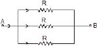
Ex.18 Find equivalent Resistance
Sol. 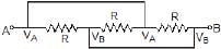
Here all the Resistance are connected between the terminals A and B. So, Modified circuit is
So Req= 
Ex.19 Find the current in Resistance P if voltage supply between A and B is V volts
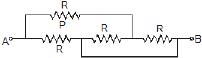
Sol. Req = 
I =  Modified circuit
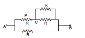
Current in  =
= 
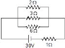
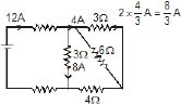
Ex.20 Find the current in 2 W resistance.
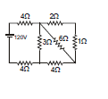
Sol. 2?, 1? in series = 3?
3?, 6? in parallel = 
2?, 4? in series = 6?
6?, 3? is parallel = 2?
Req = 4 + 4 + 2 = 10 ?

So current in 2 ? Resistance = 
special problems
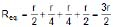
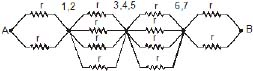
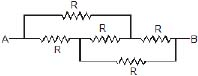
We wish to determine equivalent resistance between A and B. In figure shown points (1,2) (3, 4, 5) and (6, 7) are at same potential Equivalent circuit can be redrawn as in figure shown.
The equivalent resistance of this series combination is

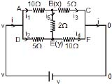
In the figure shown, the resistances specified are in ohms. We wish to determine the equivalent resistance between point A and D. Point B and C, E and F are the the same potential so the circuit can be redrawn as in figure shown.
Thus the equivalent resistance is 1 ?.
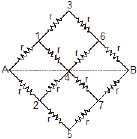
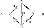
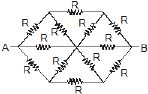
 In the network shown in figure shown all the resistances are equal, we wish to determine equivalent resistance between A and E. Point B and D have same potential, similarly F and H have same potential. The equivalent circuit is shown in figure shown. The equivalent resistance of network is 7R/2.
Ex.21 In the circuit shown in figure. (a) find the current flowing through the 100 W resistor connecting points U and S.
Sol. Figure (b) shows simplified circuit. The battery is directly attached to resistor 90W hence current in it is 2 A, see figure (c), The total resistance of second branch is also 90 W, hence current divides equally. Now current through 45 W resistor is 2 A and it is a combination of two equal 90 W resistors. Once again current divides equally. 90 W resistor is a series combination of 40 W and 50 W, hence current through them is equal, i.e.,
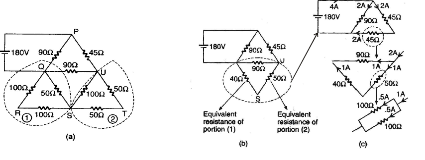
1 A. As 50 ? resistor is a parallel combination of two equal 100 ? resistors, they must have the same current i.e., 0.5 A
==================================================================
Wheatstone Bridge - Current Electricity, Class 12, Physics
8. Wheatstone's Bridge
(i) Wheatstone designed a network of four resistances with the help of which the resistance of a given conductor can be measured. Such a network of resistances is known as Wheastone's bridge.
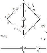
(ii) In this bridge, four resistance P, Q, R and S are so connected so as to form a quadrilateral ABCD. A sensitive galvanometer and key K2 are connected between diagonally opposite corners B and D, and a cell and key K1 are connected between two other corners A and C (figure shown)
(iii) When key K1 is pressed, a current i flows from the cell. On reaching the junction A, the current i gets divided into two parts i1 and i2. Current i1 flows in the arm AB while i2 in arm AD. Current i1, on reaching the junction B gets further divided into two parts (i1 - ig) and ig, along branches BC and BD respectively. At junction D, currents i2 and ig are added to give a current (i2 ig), along branch DC. (i2 - ig) and (i2 ig) add up at junction C to give a current (i1 i2) or i along branch CE. In this way, currents are distributed in the different branches of bridge. In this position, we get a deflection in the galvanometer.
(iv) Now the resistance P,Q,R and S are so adjusted that on pressing the key K2, deflection in the galvanometer becomes zero or current ig in the branch BD becomes zero. In this situation, the bridge is said to be balanced.
(v) In this balanced position of bridge, same current i1 flows in arms AB and BC and similarly same current i2 in arms AD and DC. In other words, resistances P and Q and similarly R and S, will now be joined in series.
(vi) Condition of balance : Applying Kirchhoff's 2nd law to mesh ABDA, i1P + igG - i2R = 0 ...(1)
Similarly, for the closed mesh BCDB, we get, (i1 - ig) Q - (i2 + ig)S - igG = 0 ...(2) When bridge is balanced, ig = 0. Hence eq. (1) & (2) reduce to
i1P - i2R = 0 or i1P = i2R ....(3)
i1Q - i2S = 0 or i1Q = i2S ...(4)
Dividing (3) by (4), we have,  ....(5)
This is called as condition of balanced for Wheatstone's Bridge.
(vii) It is clear from above equation that if ratio of the resistance P and Q, and the resistance R are known, then unknwon resistance S can be determined. This is the reason that arms P and Q are called as ratio arms, arm AD as known arm and arm CD as unknown arm.
(viii) When the bridge is balanced then on inter-changing the positions of the galvanometer and the cell there is no effect on the balance of the bridge. Hence the arms BD and AC are called as conjugate arms of the bridge.
(ix) The sensitivity of the bridge depends upon the value of the resistances. The sensitivity of bridge is maximum when all the four resistances are of the same order.
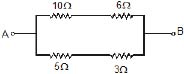
Ex.22 Find equivalent resistance of the circuit between the terminals A and B.
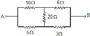
Sol. Since the given circuit is wheat stone bridge and it is in balance condition.
Because, 10 × 3 =30 = 6× 5
hence this is equivalent to

Ex.23 Find the equivalent resistance between A and B
Sol. This arrangement can be modified as shown in figure since it is balanced wheat stone bridge.

8.1 Unbalanced Wheatstone Bridge
Ex.24
Find equivalent resistance ?
Sol. Let potential at point B is x and E is Y

Applying KCl at point B
8x - 5y = v ...(1)
Applying KCL at point E
⇒ 8y - 5x = 2v ...(2)
solving x & y  ,
, 
current from branches BC & EF adds up to give total current (i) flowing in the circuit.
i = i3 i4 =  =
= 
Because,  Therefore, Req. =
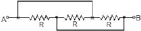
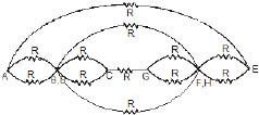
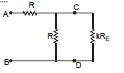
Ladder Problem :
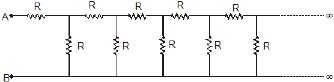
Find the effective resistance between A & B ?
Sol. Let the effective resistance between A & B be RE since the network is infinite long, removal of one cell from the chain will not change the network. The effective resistance between points C & D would also be RE.
The equivalent network will be as shown below
The original infinite chain is equivalent to R in series with R & RE in parallel.

RER + RE2 = R2 + 2RRE ⇒ RE2 - RRE - R2 = 0

Ex.25
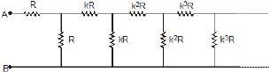
Find the equivalent resistance between A & B ?
Sol. As moving rom one section to next one, resistance is increasing by k times. Since the network is infinitely long, removal of one section from the chain will bring a little change in the network. The effective resistance between points C & D would be kRE (where RE is the effective resistance)
Therefore, Effective R between A & B.

On solving we get
15. Symmetrical Circuits :
Some circuits can be modified to have simpler solution by using symmetry if they are solved by traditional method of KVL and KCL then it would take much time.
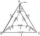
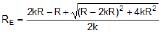
Ex.26 Find the equivalent Resistance between A and B
Sol. I Method : mirror symmetry
The branches AC and AD are symmetrical
Therefore, current through them will be same.
The circuit is also similar from left side and right side like mirror images with a mirror placed alone CD therefore current distribution while entering through B and an exiting from A will be same. Using all these facts the currents are as shown in the figure. It is clear that current in resistor between C and E is 0 and also in ED is 0. It's equivalent is shown in figure (b)

II Method : folding symmetry
Therefore, The potential difference in R between (B, C) and between (B, D) is same VC = VD
Hence the point C and D are same hence circuit can be simplified as
This is called folding.
Now , it is Balanced Wheatstone bridge

 In II Method it is not necessary to know the currents in CA and DA
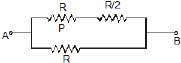
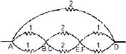
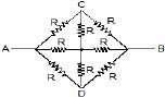
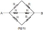
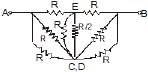
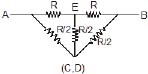
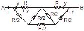
Ex.27 Find the equivalent Resistance between A and B
Sol. In this case the circuit has symmetry in the two branches AC and AD at the input
Therefore, current in them are same but from input and from exit the circuit is not similar
(Because, on left R and on right 2R)
Therefore, on both sides the distribution of current will not be similar.
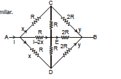
Here Vc = Vd
hence C and D are same point
So, the circuit can be simplified as
Now it is balanced wheat stone bridge.
 =
= 
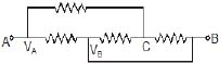
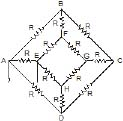
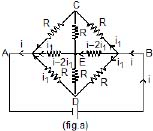
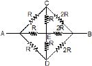
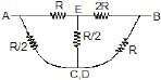
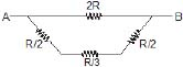
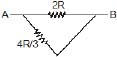
Ex.28 Find the equivalent Resistance between A and B
Sol. 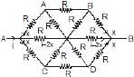
Here VA = VC and VB = VD
Here the circuit can be simplified as
 =
= 
Ans. 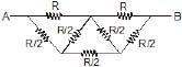
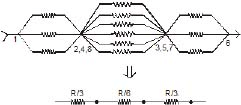
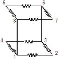
Ex.29 Twelve equal resistors each R W are connected to form the edges of a cube. Find the equivalent resistances of the network.
(a)When current enters at 1 & leaves at 6 (body diagonal)
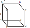
Sol. Here 2, 4, 8 are equipotential points (if we move from 1 → 2, 4, 8 it comes along the edge & 6 → 2, 4, 8 it comes along face diagonal). Similarly 3, 5, 7 are equipotential points.

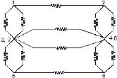
(b) When current enters at 1 and leaves at 2
Sol. Here 3, 7 are equipotential surface (if we move from 1 → 3, 7 we have along face and 2, →3, 7 we move along edge) similarly 4, 8 are equipotential surface.

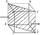
(c) When current enters at 1 and leaves at 3
Sol. If we cut the cube along the plane passing through 2, 4, 5, 7 then by mirror symmetry, the final configuration will be

===========================================================================
Combinations of Cells - Current Electricity, Class 12, Physics
9. Combinations of cells
A cell is used to maintain current in an electric circuit. We cannot obtain a strong current from a single cell. Hence need arises to combine two or more cells to obtain a strong current. Cells can be combined in three possible ways:
(A) In series, (B) In parallel, and (C) In mixed grouping.
(A) Cells in Series
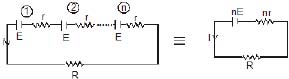
In this combination, cells are so connected that -ve terminal of each cell is connected with the ve terminal of next and so on. Suppose n cells are connected in this way. Let e.m.f and internal resistance of each cell are E and r respectively.
Net e.m.f of the cells = nE. Total internal resistance = nr. Hence total resistance of the circuit = nr + R.
If total current in the circuit is I, then 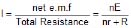 ...(1)
Case (i) : If nr < < R, then  i.e., if total internal resistance of the cells is far less than external resistance, then current obtained from the cells is approximately equal to n times the current obtained from a single cell. Hence cells, whose total internal resistance is less than external resistance, just be joined in series to obtain strong current.
Case (ii) : If nr >> R, then  i.e., if total internal resistance of the cells is much greater than the external resistance, then current obtained from the combination of n cells is nearly the same as obtained from a single cell. Hence there is no use of joining such cells in series.
(B) Cells in Parallel
(I) When E.M.F's and internal resistance of all the cells are equal : In this combination, positive terminals of all the cells are connected at one point and negative terminals at other point. Figure shown such cells connected in parallel across some external resistance R. Let e.m.f and internal resistance of each cell are E and r respectively.
Because all the cells are connected in parallel between two points, hence e.m.f of battery = E.
Total internal resistance of the combination of n cells = r/n
Because external resistance R is connected in series with internal resistance, hence total resistance of the circuit = (r/n) R
If current in external resistance is I, then
 =
= 
Case (I) : If r << R, the  i.e., if internal resistance of the cells is much less than external resistance, then total current obtained from combination is nearly equal to current given by one cells only. Hence there is no use of joining cells of low internal resistance in parallel.
Case (II) : If r >> R, then  i.e., if the internal resistance of the cells is much higher than the external resistance, then total current is nearly equal to n times the current given by one cell. Hence cells of high internal resistance must be joined in parallel to get a strong current.
(II) When emf's and internal resistance of all the cells connected in parallel are different.
In this case, total current in external resistance is obtained with the help of Kirchhoff's laws. Figure shows three cells of e.m.f E1, E2 and E3 and internal resistances r1, r2 and r3 connected in parallel across some external resistance R. Suppose currents given by three cells are i1, i2 and i3. Hence according to Kirchhoff's first law, total current I in external resistance R, is given by
I = i1 i2 i3 ...(1)
Applying Kirchhoff's 2nd law to closed mesh ABEF we get
IR i1r1 = E1 or i1 =  ...(2)
Similarly, for closed meshes ABDG and ABCH, we get 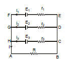
 ....(3)
and  ....(4)
Substituting eq. (2), (3) and (4) in eq. (1), we have
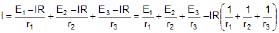
or 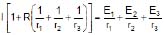 or
or 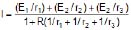
If n cells are joined in parallel, then  and Eeq.
 , req.
(C) Cells in Mixed Grouping
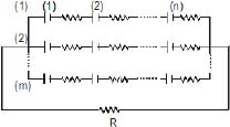
In this combination, a certain number of cells are joined in series in various rows, and all such rows are then connected in parallel with each other.
Suppose n cells, each of e.m.f E and internal resistance r, are connected in series in every row and m such rows are connected in parallel across some external resistance R, as shown in figure.
Total number of cells in the combination = mn. As e.m.f. of each row = nE and all the rows are connected in parallel, hence net e.m.f of battery = nE.
Internal resistance of each row = nr. As m such rows are connected in parallel, hence total internal resistance of battery = 
Hence total resistance of the circuit = 
If the current in external resistance is I, then
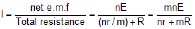
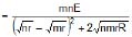
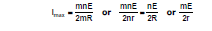
It is clear from above equation that I will be maximum when

This will be possible when the quantity [Önr - ÖmR]2 is minimum. Because this quantity is in square, it can not be negative, hence its minimum value will be equal to zero, i.e.,
mR = nr or R = 
i.e., In mixed grouping of cells, current in external resistance will be maximum when total internal resistance of battery is equal to external resistance.
 Because power consumed in the external resistance or load = I2R, hence when current in load is maximum, consumed power in it is also maximum, Hence consumed power in the load will also be maximum when R =
  .
.
Ex.30 Find the current in the loop.
Sol. The given circuit can be simplified as

=  ⇒
⇒ 
Ex.31 Find the emf and internal resistance of a single battery which is equivalent to a combination of three batteries as shown in figure.
Sol. 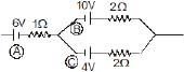
Battery (B) and (C) are in parallel combination with opposite polarity. So, their equivalent
rBC = 1 W
Now, 
rABC = 2? Ans.
===============================================================
Electrical Power - Current Electricity, Class 12, Physics
10. Electrical power
The energy liberated per second in a device is called its power, the electrical power P delivered by an electrical device is given by
P =  V = VI
Power consumed by a resistor.
P = VI = I2R = 
The power P is in watts when I is in amperes, R is in ohms and V is in volts.
The practical unit of power is 1 kW = 1000 W.
The formula for power P = I2R = VI =  is true only when all the electrical power is dissipated as heat and not converted into mechanical work, etc. simultaneously.
If the current enters the higher potential point of the device then electric power is consumed by it (i.e. acts as load). If the current enters the lower potential point then the device supplies power (i.e. acts as source.)
(a) Joule's law of electrical heating
When an electric current flows through a conductor electrical energy is used in overcoming the resistance of the wire. If the potential difference across a conductor of resistance R is V volt and if a current of I ampere flows the energy expanded in time t seconds is given by
W = VIt joule
= I2Rt joule = 
The electrical energy so expanded is converted into heat energy and this conversion is called the heating effect of electric current.
The heat generated in joules when a current of I amperes flows through a resistance of R ohm for t seconds is given by
This relation is known as Joule's law of electrical heating.
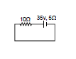
Ex.32 If bulb rating is 100 watt and 220 V then determine
(a) Resistance of filament
(b) Current through filament
(c) If bulb operate at 110 volt power supply then find power consume by bulb.
Sol. Bulb rating in 100 W and 220 V bulb means when 220 V potential difference is applied between the two ends then the power consume is 100 W
Here V = 220
P = 100

So R = 484 W
Since Resistance depends only on material hence it is constant for bulb
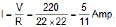
power consumed at 110 V
Therefore, power consumed = 
Ex.33 In the following figure, grade the bulb in order of their brightness :
Sol. 


Power = i2R
As current passing through every bulb is same
Therefore, Brightness order is B3 > B2 > B1
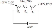
Ex.34
The above configuration shows three identical bulbs, Grade them in order of their brightness.
Sol. B1 & B2 withdraw less current as compared to B3 because in series they give 2R resistance where as R is the resistance dut to B3.
Power = i2R
Therefore, Brightness order : B3 > B2 = B1.
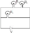
Ex.35
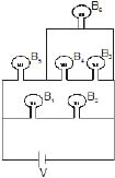
Grade the bulbs in order of their brightness (All bubls are identical)
Sol.
Therefore, Order of Brightness : B5 > B1 = B2 > B6 > B4 = B3
(B) Maximum power transfer theorem
Let E be emf and r internal resistance of the battery. It is supplying current to an external resistance R
current in circuit I = 
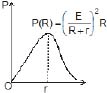
The power absorbed by load resistor R is
P = I2R = 
For maximum power transfer we take the derivative of P w.r.t R, set it equal to zero and solve the equation for R.
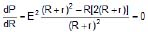
Solving for R, we have
(R r)2 - R (2) (R r) = 0 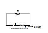
(R r) - 2R = 0
R = r
For a given real battery the load resistance maximizes the power if it is equal to the internal resistance of the battery.
The maximum power transfer theorem in general, holds for any real voltage source. The resitance R may be a single resistor or R may be the equivalent resistance of a collection of resistors.
11. Instruments
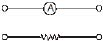
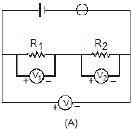
(a) Ammeter
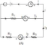
It is a device used to measure current and its always connected in series with the 'element' through which current is to be meaured, e.g., in figure (A) ammeter A1will measure the current (I1) through resistance R1, A2 measures current (I2) through R2 and R3 while A, measures current I( I1 + I2).
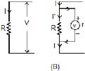
Regarding an ammeter it is worth noting that :
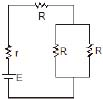
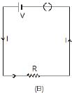
(1) The reading of an ammeter is always lesser than actual current in the circuit, e.g., true current in the resistance R in the circuit shown in figure (B) is I = 
However, when an ammeter of resistance r is used to measure current as shown in figure (C), the reading will be

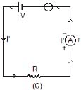
(2) Smaller the resistance of an ammeter more accurate will be its reading. An ammeter is said to be ideal if its resistance (r) is zero. However, as practically r ¹ 0, ideal ammeter cannot be realised in practice.
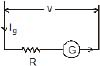
(3) To convert a galvanometer into an ammeter of a certain range say I, a small resistance S (called shunt) is connected in parallel with the galvanometer so that the current passing through the galvanometer of resistance G becomes equal to its full scale deflection value Ig. This is possible only if
i.e., 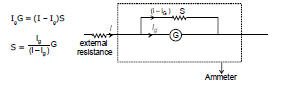
Ex.36 What is the value of shunt which passes 10% of the main current through a galvanometer of 99 ohm?
Sol. As in figure RgIg = (I - Ig)S
⇒ 

⇒ S = 11 ?
For calculation it is simply a resistance
Resistance of ammeter

for S << RG ⇒ RA = S
Ex.37 Find the current in the circuit also determine percentage error in measuring in current through an ammeter (a) and (b).
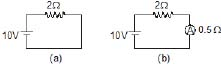
Sol. In A 
In B 
Percentage error is =  = 20% Ans.
Here we see that due to ammeter the current has reduced. A good ammeter has very low resistance as compared with other resistors, so that due to its presence in the circuit the current is not affected.
Ex.38 Find the reading of ammeter. Is this the current through 6 W ?
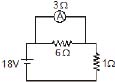
Sol. 
Current through battery

So, current through ammeter

No, it is not the current through the 6? resistor.
 Ideal ammeter is equivalent to zero resistance wire for calculation potential difference across it is zero.
(b) Voltmeter
It is a device used to measure potential difference and is
always put in parallel with the 'circuit element' across which potential difference is to be measured e.g., in Figure (A) voltmeter V1 will measure potential difference across resistance R1, V2 across resistance R2 and V across (R1 R2) with V = V1 V2
Regarding a voltmeter it is worth noting that :
(1)The reading of a voltmeter is always lesser than true value, e.g., if a current I is passing through a resistance R [Fig. (B)], the true value V = IR. However, when a voltmeter having resistance r is connected across R, the current through R will become
 and so
and as voltmeter is connected across R its reading V' is lesser than V.
(2) Greater the resistance of voltmeter, more accurate will be its reading. A voltmeter is said to be ideal if its resistance r is infinite, i.e., it draws no current from the circuit element for its operation. Ideal voltmeter has been realised in practice in the form of potentiometer.
(3) To convert a galvanometer into a voltmeter of certain range say V, a high resistance R is connected in series with the galvanometer so that current passing through the galvanometer of resistance G becomes equal to its full scale deflection value Ig. This is possible only if
V = Ig (G R) i.e., 
Ex.39 A voltmeter has a resistance of G ohm and range of V volt. Calculate the resistance to be used in series with it to extend its range to nV volt.
Sol. Full scale current ig = 
to change its range
V1 = (G Rs) ig
⇒ nV = (G Rs) 
Rs = G(n - 1) Ans.
Ex.40 Find potential difference across the resistance 300 W in A and B.
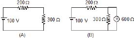
Sol. In (A) : Potential difference =  = 60 volt
In (B) Potential difference = 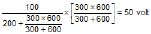
We see that by connected voltmeter the voltage which was to be measured has charged. Such voltmeters are not good. If its resistance had been very large than 300 W then it would have not affected the voltage by much amount.
=====================================================================
Meter Bridge and PotentioMeter - Current Electricity, Class 12, Physics
(C) METRE-BRIDGE
Metre-bridge is a sensitive device based on the principle of wheatstone-bridge, for the determination of the resistance of a conductor (wire). Its sensitivity is much more than that of the post-office box.
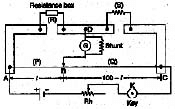
Metre-bridge is shown in figure AC is one metre long wire of manganin or constantan which is fixed along a scale on a wooden base. The area of cross-section of the wire is same at all places. The ends A and C of the wire are joined to two L-shaped copper strips carrying binding-screws as shown. In between these strips, leaving a gap on either side, there is a third copper strip having three binding screws. The middle screw D is connected to a sliding jockey B through a shunted - galvanometer G. The knob of the jockey can be made to touch at any point on the wire.
To measure the unknown resistance, the connection as shown in figure are made.
A resistance R is taken out from the resistance box and the key K is closed. Now the jockey is slided along the wire and a point is determined such that, on pressing the jockey on the wire at that point there is no deflection in the galvanometer G. In this position the points B and D are at the same potential. The point B is called 'null-point'. The lengths of both the parts AB and BC of the wire are read on the scale. Suppose the resistance of the length AB of the wire is P and that of the length BC is Q. Then, by the principle of Wheastone-bridge. We have,

Let the length AB be l cm. Then the length BC will be = (100 - l) cm.
Therefore, resistance of AB, i.e. P =  , and resistance of BC, Q = r (100 - l)/A
where r is the specific resistance of the material of the wire and 'A' is the area of cross-section of the wire. Thus
 ...(i)
Substituting this value of  in eq. (i), we get
 or
or 
R is the resistance taken in the resistance box and l is the length measured. Hence, the value of resistance S can be determined from the above formula.
A number of observations are taken for different resistances in the resistance box and for each observation the value of S is calculated.
Finally, the experiment is repeated by interchanging the unknown resistances S and the resistance box. The mean of the values of S is then obtained.
Ex.41 In a meter bridge experiment, the value of unknown resistance is 2W. To get the balancing point at 40 cm distance from the same end, then what will be the resistance in the resistance box ?
Sol. Apply condition for balance wheat stone bridge,
, P = 3 ? Ans.
(D) Potentiometer
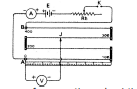
A potentiometer is used to compare e.m.fs. of two cells or to measure internal resistance of a cell.
Principle : The potentiometer is based upon the principle that when a constant current is passed through a wire of uniform area of cross-section, the potential drop across any portion of the wire is directly proportional to the length of that portion.
Construction : A potentiometer consists of a number of segments of wire of uniform area of cross section stretched on a wooden board between two thick copper strips. Each segment of wire is 100 cm long. The wire is usually of constantan or manganin. A metre rod is fixed parallel to its length. A battery connected across the two end terminals sends current through the wire, which is kept constant by using a rheostat.
Theory : Let V be potential difference across certain portion of wire, whose resistance is R. If I is the current through the wire, then V = IR
We know that R =  ,
,
where l, A and r are length, area of cross-section and resistivity of the material of wire respectively.
Therefore, 
If a constant current is passed through the wire of uniform area of cross-section, then I and A are constants. Since, for a given wire, r is also constant, we have
V = constant × l
or V is directly proportional to l
Hence, if a constant current flows through a wire of uniform area of cross-section, then potential drop along the wire is directly proportional to the length of the wire.
Applications of a potentiometer. A potentiometer can be put to following uses :
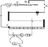
1. To compare e.m.fs. of two cells : Two cells, whose e.m.fs. are E1 and E2, can be compared by making use of the ciruit as shown in figure. The positive poles of both the cells are connected to the terminal A of the potentiometer. The negative poles of the two cells are connected to terminals 1 and 2 of a two way key. while its common terminal is connected to a jockey j through a galvanometer G. An auxiliary or driver battery of e.m.f E¢, an ammeter A, rheostat Rh and a one way key K are connected between the end terminals A and B of the potentiometer. Thus, the positive poles of the two cells as well as the positive pole of auxiliary battery are connected at the common point A. It may be pointed that the e.m.f of auxiliary battery should always be greater than the e.m.f of either of the two cells.
To compare the e.m.fs of the two cells, a constant current is passed through the potentiometer wire between points A and B. The current is kept constant by using the rheostat.
When the plug is put in the gap between the terminals 1 and 3 of the two way key, the cell of e.m.f. E1 will come in the ciruit. Suppose the balancing length (between points A and J) is l1. If x is the resistance per unit length of the potentiometer wire and I, the constant current flowing through it, then
E1 = (xl1) I
When the key is put in the gap between the terminals 2 and 3 and removed from the gap between 1 and 3, the cell of e.m.f E2 wil be included in the circuit. Let the balancing length be l2 in this case. Then,
E2 = (x l2) I
Dividing above equation

Note : It may be pointed out that the e.m.f of auxiliary battery should always be greater than the e.m.f. of the either of the two cells.
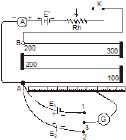
2. To measure internal resistance of a cell. The internal resistance of a cell may be found by using a potentiometer by setting up the circuit as shown in figure.
A constant current I is maintained through the potentiometer wire with the help of the rheostat.
Plug in the key K2 is kept out and the jockey is moved over the potentiometer wire so as to balance the e.m.f. E of the cell, whose internal resistance is to be found. Let l1 be the balancing length of the potentiometer wire between point A and jockey J. If x is resistance per unit length of the wire, then
E = (x l1) I
With the help of resistance box S, introduce resistance say S and then put the plug in key K2. Now find the balance point for the terminal potential difference V between the two poles of the cell. If l2 is the balancing length, then
V = (x l2) I
Dividing above equation , we have

The internal resistance* of the cell is given by

Using above equation , we have
 or
or 
Knowing the values of l1, l2 and S, the internal resistance r of the cell can be found.
Note : Apart from uses, a potentiometer can be used to compare unknown resistances and to calibrate a voltmeter or an ammeter.
We use potentiometer for two tasks :
(i) to find emf of a cell
(ii) to find internal resistance of a celll
We will first analyse the first task → to find emf of a cell through some examples
Ex.42
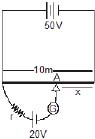
Find the value of x if A is the null point ?
Sol.
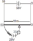
Potential gradient =  = 5 V/m
Therefore, For 20V potential difference


FAQs on CURRENT ELECTRICITY, Chapter Notes, Class 12, Physics, (IIT-JEE & AIPMT)
| 1. What is current electricity? |  |
| 2. What is the difference between AC and DC current? | |
| 3. What is Ohm's law? | |
| 4. What is a circuit diagram? | |
| 5. What is the difference between a resistor and a conductor? | |


