Chapter - Network Theorems, PPT, DC Circuits, Semester, Engineering - Electronics and Communication Engineering (ECE) PDF Download

Introduction
The slides cover the following topics:
- Network Theorem
- Superposition Theorem
- Thevenin and Norton Equivalent Circuits
- Norton's Theorem
- Maximum Power Transfer
- Circuit Transformation
Networks Theorem---------------------------------------------------Next slide
Network Theorems
Networks Theorem---------------------------------------------------Next slide
Objectives
- apply the superposition theorem for circuit analysis
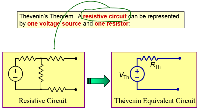
- apply Thevenin’s theorem to simplify the circuit for analysis
- apply Norton’s theorem to simplify the circuit for analysis
- understand maximum power transfer and perform circuit conversion
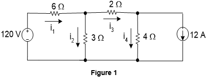
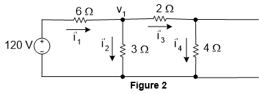
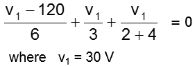
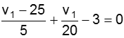
The equations for the current in each branch,
Networks Theorem---------------------------------------------------Next slide
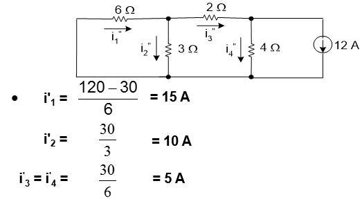
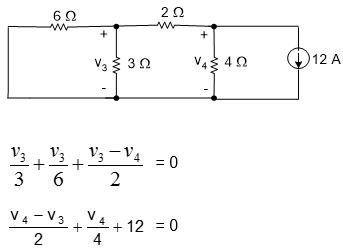
In order to calculate the current cause by the current source, we deactivate the ideal voltage source with a short circuit, as shown
Networks Theorem---------------------------------------------------Next slide
Networks Theorem---------------------------------------------------Next slide
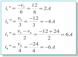
Now we can find the branches current,
Networks Theorem---------------------------------------------------Next slide
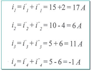
To find the actual current of the circuit, add the currents due to both the current and voltage source,
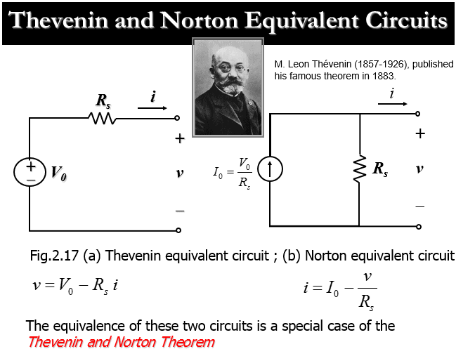
Thevenin & Norton Equivalent Circuits
A series combination of Thevenin equivalent voltage source V0 and Thevenin equivalent resistance Rs
A parallel combination of Norton equivalent current source I0 and Norton equivalent resistance Rs
Networks Theorem---------------------------------------------------Next slide
Networks Theorem---------------------------------------------------Next slide
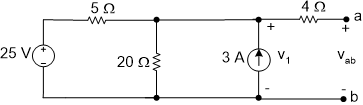
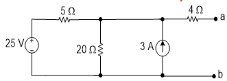
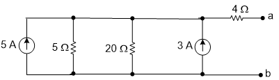
Refer to the Figure 6, find the Thevenin equivalent circuit.
Networks Theorem---------------------------------------------------Next slide
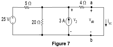
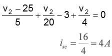
Current isc can be found if v2 is known. By using the bottom right node as the reference node, the equationfor v2 becomes
By solving the above equation, v2 = 16 V. Therefore, the short circuit current isc is
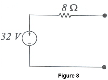
The Thevenin resistance RTh is
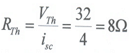
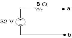
Figure 8 shows the Thevenin equivalent circuit for the Figure 6.
Networks Theorem---------------------------------------------------Next slide
Networks Theorem---------------------------------------------------Next slide
Norton’s Theorem
Example 3
Derive the Thevenin and Norton equivalent circuits of Figure 6.
Networks Theorem---------------------------------------------------Next slide
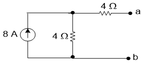
Step 2: Combination of parallel source and parallel resistance
Step 3: Source transformation (combined serial resistance to produce the Thevenin equivalent circuit.)
Networks Theorem---------------------------------------------------Next slide
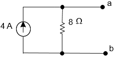
Figure 9 Steps in deriving Thevenin and Norton equivalent circuits.
Networks Theorem---------------------------------------------------Next slide
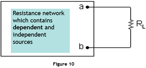
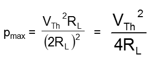
Maximum Power Transfer
Networks Theorem---------------------------------------------------Next slide
Circuit Transformation
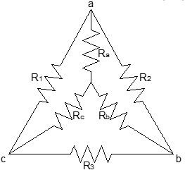
Figure 12 Delta and Star Circuit Connection
Networks Theorem---------------------------------------------------Next slide
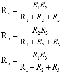
Delta (Δ) to star (Y) transformation:
Networks Theorem---------------------------------------------------Next slide
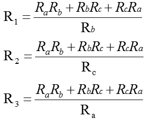
Star (Y) to Delta (D) transformation:
Networks Theorem---------------------------------------------------Next slide
Objectives
- apply the superposition theorem for circuit analysis
- apply Thevenin’s theorem to simplify the circuit for analysis
- apply Norton’s theorem to simplify the circuit for analysis
- understand maximum power transfer and perform circuit conversion
FAQs on Chapter - Network Theorems, PPT, DC Circuits, Semester, Engineering - Electronics and Communication Engineering (ECE)
| 1. What are the different network theorems covered in the chapter? |  |
| 2. How can I apply Kirchhoff's laws to solve a DC circuit? | |
| 3. How does Thevenin's theorem simplify circuit analysis? | |
| 4. What is the purpose of the Maximum Power Transfer theorem? | |
| 5. How does the Superposition theorem simplify circuit analysis? | |


Top Courses for Electronics and Communication Engineering (ECE)
Semester
,Engineering - Electronics and Communication Engineering (ECE)
,video lectures
,shortcuts and tricks
,Summary
,Previous Year Questions with Solutions
,Chapter - Network Theorems
,DC Circuits
,Exam
,Extra Questions
,Chapter - Network Theorems
,Viva Questions
,past year papers
,DC Circuits
,Engineering - Electronics and Communication Engineering (ECE)
,Semester Notes
,PPT
,DC Circuits
,Engineering - Electronics and Communication Engineering (ECE)
,Semester
,Sample Paper
,practice quizzes
,MCQs
,PPT
,Important questions
,Free
,study material
,Objective type Questions
,mock tests for examination
,Chapter - Network Theorems
,Semester
,PPT
,ppt
;


Chapter - Network Theorems, PPT, DC Circuits, Semester, Engineering Free PDF Download
Importance of Chapter - Network Theorems, PPT, DC Circuits, Semester, Engineering
Chapter - Network Theorems, PPT, DC Circuits, Semester, Engineering Notes
Chapter - Network Theorems, PPT, DC Circuits, Semester, Engineering Electronics and Communication Engineering (ECE) Questions
Study Chapter - Network Theorems, PPT, DC Circuits, Semester, Engineering on the App
|
© EduRev
|
Education Revolution
|


|


within 7 days!