Chapter : Diodes And Diode Circuits, PPT, Semester, Engineering - Electronics and Communication Engineering (ECE) PDF Download

Diodes and Diode Circuits
Diodes and Diode Circuits ------------------------------------------------------------------------------ Next Slide
Diode Characteristics
• A diode is simply a pn junction, but its applications are extensive in electronic circuits.
• Three important characteristics of a diode are:
– Forward voltage drop
• Forward Bias, about .7 volts
– Reverse voltage drop.
• Depletion layer widens, usually the applied voltage
– Reverse breakdown voltage.
• Reverse voltage drop that will force current flow and in most cases destroy the diode.
Diodes and Diode Circuits ------------------------------------------------------------------------------ Next Slide
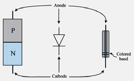
Diode Elements
• A diode has two leads connected to the external circuit.
• Since a diode behaves differently depending upon forward or reverse bias, it is critical to be able to distinguish the leads.
• The anode connects to the p-type material, the cathode to the n-type material of the diode
Diodes and Diode Circuits ------------------------------------------------------------------------------ Next Slide
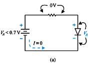
Ideal Diodes
• In an ideal diode, current flows freely through the device when forward biased, having no resistance.
• In an ideal diode, there would be no voltage drop across it when forward biased. All of the source voltage would be dropped across circuit resistors.
• In an ideal diode, when reverse biased, it would have infinite resistance, causing zero current flow.
Diodes and Diode Circuits ------------------------------------------------------------------------------ Next Slide
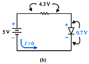
Practical Diodes
• A practical diode does offer some resistance to current flow when forward biased.
• Since there is some resistance, there will be some power dissipated when current flows through a forward biased diode. Therefore, there is a practical limit to the amount of current a diode can conduct without damage.
• A reverse biased diode has very high resistance.
• Excessive reverse bias can cause the diode to conduct
Diodes and Diode Circuits ------------------------------------------------------------------------------ Next Slide
Practical Diode Forward Bias
Diodes and Diode Circuits ------------------------------------------------------------------------------ Next Slide
Practical Diode Forward Bias
Diodes and Diode Circuits ------------------------------------------------------------------------------ Next Slide
Practical Diode Forward Bias
Diodes and Diode Circuits ------------------------------------------------------------------------------ Next Slide
Reverse Bias
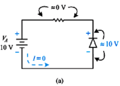
Diodes and Diode Circuits ------------------------------------------------------------------------------ Next Slide
Reverse Bias
Diodes and Diode Circuits ------------------------------------------------------------------------------ Next Slide
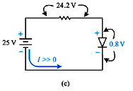
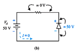
Exceed Breakdown Voltage
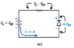
Diodes and Diode Circuits ------------------------------------------------------------------------------ Next Slide
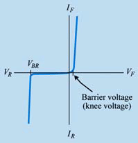
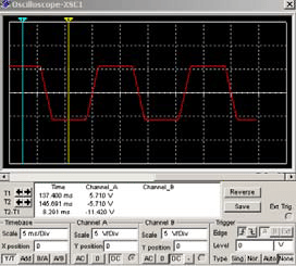
Current versus Voltage
• In a practical diode, there is very little forward current until the barrier voltage is reached.
• When reverse biased, only a small amount of current flows as long as the reverse voltage is less than the breakdown voltage of
the device.
Diodes and Diode Circuits ------------------------------------------------------------------------------ Next Slide
Power Supply Applications
• Nearly all computers have some sort of power supply.
• Power supply circuits must:
– Convert the ac line voltage into a dc voltage required by the circuit.
– Reduce the ac voltage to a lower value.
– Continuously adjust the dc output voltage to keep it constant under varying load conditions.
Diodes and Diode Circuits ------------------------------------------------------------------------------ Next Slide
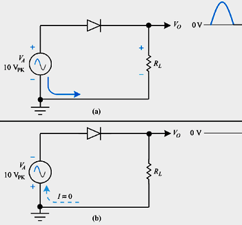
Half-wave Rectifier
• The term rectify is used to describe the conversion of ac into dc.
• In the circuit shown, only one-half of the input waveform is allowed to pass through to the output.
• This is called half-wave rectification.
Diodes and Diode Circuits ------------------------------------------------------------------------------ Next Slide
Circuit Operation
• During the positive alternation, the diode is forward biased and the full applied voltage is dropped across the load resistor.
• During the negative alternation, the diode is reverse biased and acts like an open circuit. No voltage is present across the load resistor.
• The output voltage is actually pulsating dc.
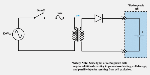
• An application for a half-wave rectifier is shown on the following slide.
Diodes and Diode Circuits ------------------------------------------------------------------------------ Next Slide
Circuit Operation
12:1 ratio, about 10 volts rms or 14.1 VP
Pulsating DC = VP / π, or .318 x VP in this case 4.48 VDC average (formula not in text)
Diodes and Diode Circuits ------------------------------------------------------------------------------ Next Slide
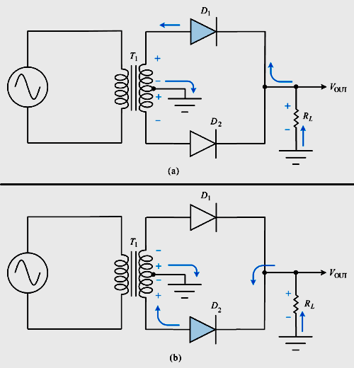
Full-wave Rectifier
• A full-wave rectifier applies both halves of an ac waveform to the output.
• The circuit shown is called a biphase half-wave rectifier and sometimes a center-tapped rectifier circuit.
• Operation of a full-wave rectifier is demonstrated in the figure shown on the following slide.
Diodes and Diode Circuits ------------------------------------------------------------------------------ Next Slide
Full-wave Rectifier
Diodes and Diode Circuits ------------------------------------------------------------------------------ Next Slide
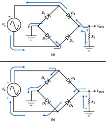
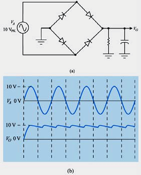
Bridge Rectifier
• A bridge rectifier is more widely used than the center-tapped rectifier.
• Circuit operation is best understood by examining the current paths of the forward and reverse biased diodes during each
half-cycle of the input waveform.
Diodes and Diode Circuits ------------------------------------------------------------------------------ Next Slide
Filter Networks
• Most electronic applications require smooth dc current to operate properly. Filtering pulsating dc circuits accomplishes this.
• Adding a capacitor to the output of a half-wave rectifier filters the pulsating dc into smooth dc.
• Ripple-----
Diodes and Diode Circuits ------------------------------------------------------------------------------ Next Slide
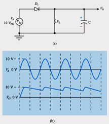
Full-wave Rectifier with Filter
• A capacitive filter added to the output of a full-wave bridge rectifier is shown at the right.
• One drawback of a halfwave rectifier is the higher level of ripple voltage after filtering. Full-wave rectification reduces this
ripple voltage.
Diodes and Diode Circuits ------------------------------------------------------------------------------ Next Slide
Other Types of Filtering
• Simple capacitor filtering is adequate for many electronic applications.
• In more critical applications, more complex filter networks are required to reduce or eliminate ripple voltage
• Examples of more complex filters are:
– L filters.
• Shape of L
– Pi filters.
• Shape of π
Diodes and Diode Circuits ------------------------------------------------------------------------------ Next Slide
Miscellaneous Diode Applications
• There are many practical applications for diodes beyond power supplies.
• Some of these applications include:
– Clipper circuits that serve to protect circuits from damage as a result of over-voltage conditions.
– Clippers are common in computer circuits.
Diodes and Diode Circuits ------------------------------------------------------------------------------ Next Slide
Clipper
Diodes and Diode Circuits ------------------------------------------------------------------------------ Next Slide
Clipper
Diodes and Diode Circuits ------------------------------------------------------------------------------ Next Slide
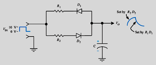
Combination Clipper
Diodes and Diode Circuits ------------------------------------------------------------------------------ Next Slide
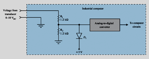
Industrial application of a Clipper Protection from high voltage input
Diodes and Diode Circuits ------------------------------------------------------------------------------ Next Slide
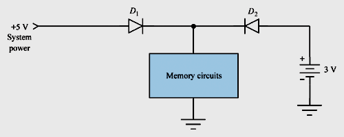
Miscellaneous Diode Applications
• Isolation diodes are used to isolate various sections of circuits from another.
• An example of this is the battery backup for computer memory.
Diodes and Diode Circuits ------------------------------------------------------------------------------ Next Slide
Miscellaneous Diode Applications
• Diodes can be used to create an RC circuit that has different time constants for charge and discharge.
• This principle is called asymmetrical time constants.
Diodes and Diode Circuits ------------------------------------------------------------------------------ Next Slide
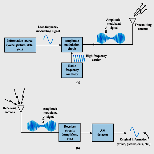
Miscellaneous Diode Applications
• Diodes can also be used as AM (amplitude modulation) detector circuits in radio receivers.
• See simulation in Multisim
Fig09_26.msm
FAQs on Chapter : Diodes And Diode Circuits, PPT, Semester, Engineering - Electronics and Communication Engineering (ECE)
| 1. What is a diode and how does it work? |  |
| 2. What are the different types of diodes? | |
| 3. How can diodes be used in circuits? | |
| 4. What are the characteristics of a diode? | |
| 5. How can I test a diode using a multimeter? | |


Top Courses for Electronics and Communication Engineering (ECE)
video lectures
,Objective type Questions
,Previous Year Questions with Solutions
,ppt
,Free
,PPT
,shortcuts and tricks
,Chapter : Diodes And Diode Circuits
,PPT
,PPT
,Important questions
,Chapter : Diodes And Diode Circuits
,Engineering - Electronics and Communication Engineering (ECE)
,Sample Paper
,MCQs
,Semester
,mock tests for examination
,Semester Notes
,study material
,Semester
,Viva Questions
,Extra Questions
,Summary
,past year papers
,Exam
,Semester
,Engineering - Electronics and Communication Engineering (ECE)
,Chapter : Diodes And Diode Circuits
,Engineering - Electronics and Communication Engineering (ECE)
,practice quizzes
;


Chapter : Diodes And Diode Circuits, PPT, Semester, Engineering Free PDF Download
Importance of Chapter : Diodes And Diode Circuits, PPT, Semester, Engineering
Chapter : Diodes And Diode Circuits, PPT, Semester, Engineering Notes
Chapter : Diodes And Diode Circuits, PPT, Semester, Engineering Electronics and Communication Engineering (ECE) Questions
Study Chapter : Diodes And Diode Circuits, PPT, Semester, Engineering on the App
|
© EduRev
|
Education Revolution
|


|


