Carburetion & Fuel Injection

Carburetion in SI engines
Carburettor is the device in a spark-ignition (SI) engine that prepares the combustible charge by atomising liquid fuel and mixing it with air in the required proportion before the mixture enters the intake manifold or cylinder. Design of a carburettor is complex because the optimum air-fuel (A/F) ratio required by the engine changes widely over different operating conditions (idle, cruising, acceleration, full load).
Variation of mixture requirement
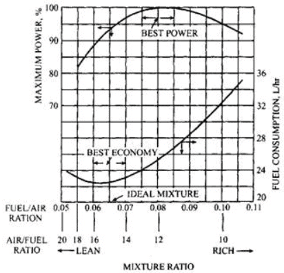
Different engine objectives require different mixtures:
- Maximum power: Requires a relatively rich mixture so that oxygen is available for rapid and complete combustion at high engine loads. Typical A/F ratio for maximum power is around 12.5 : 1; depending on engine design it may range up to about 14 : 1.
- Minimum specific fuel consumption: Achieved with a leaner mixture that improves thermal efficiency. Typical A/F ratio for minimum specific fuel consumption is about 17 : 1.
- Stoichiometric (chemically correct) mixture: For petrol, the stoichiometric A/F ratio is approximately 14.7 : 1. A mixture richer than this contains excess fuel, and a leaner mixture contains excess air.
| Range of Operation | Load | Governing Factor | A / F ratio |
|---|---|---|---|
| Idling and low load | 0-20% of rated power | Dilution of mixture by products of combustion | 12.5 : 1 (rich mixture) |
| Normal power or cruising range | 20%-75% of rated power | Fuel economy | 16.7 : 1 (slightly lean) |
| Maximum power | 75%-100% of rated power | Full utilisation of air | 14 : 1 (rich mixture) |
Simple (elementary) carburettor
The simple carburettor is intended to supply a correctly proportioned mixture over a limited speed/load range (typically cruising speed). It uses a float chamber to maintain a nearly constant fuel level and a venturi to draw fuel through a jet into the airstream.
| Operation | Governing Factor | A / F ratio |
|---|---|---|
| Starting and warm-up | Less fuel vapour due to low temperature | 3 : 1 (very rich) |
| Acceleration | Inertia of liquid fuel | Rich |
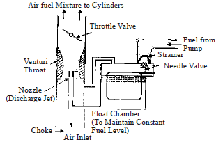
- To prevent spillage from the main nozzle, the nozzle tip is positioned slightly above the float-chamber fuel level. The vertical difference between the nozzle tip and the float chamber fuel level is called the nozzle lip.
- This simple carburettor is suitable only for a narrow operating range (cruising). Its drawbacks are that it tends to become richer as engine speed increases and may provide too lean a mixture at low loads for reliable ignition.
Fuel-air ratio in the carburettor when air compressibility is not considered
For a basic analysis ignoring air compressibility, the mass flow rates of fuel and air through the orifices determine the A/F ratio. The idealised relations between pressure drop and flow through jets give the required ratio.
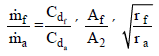
If nozzle lip Z = 0 then the simplified relation becomes:
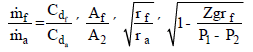
F/A ratio considering air as compressible
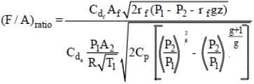

In these expressions:
- ṁf, ṁa are the mass flow rates of fuel and air respectively.
- Cdf, Cda are coefficients of discharge for the fuel nozzle and venturi throat respectively.
- Af, A2 are cross-sectional areas of the fuel nozzle and venturi throat respectively.
- ρf, ρa are densities of fuel and air respectively.
- P1, P2 are the atmospheric pressure and the pressure at the venturi throat respectively.
- Z is the nozzle lip (difference in height between the nozzle tip and the float-chamber level).
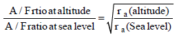
- At high altitude, air density decreases and the term involving air density in the flow expressions reduces. Unless corrected, this makes the mixture relatively richer at altitude because less air mass flows for the same venturi effect.and


- A nozzle lip is provided to avoid spilling of fuel from the nozzle during vibration or when the carburettor is not perfectly horizontal; this prevents fuel wastage and reduces fire hazard.
- Altitude compensation (for aircraft or high-altitude operation) is achieved by measures such as back-suction control or air-bleeding, which reduce the fuel delivery as air density falls so that the A/F ratio is maintained approximately constant.
- Surgingis a leakage/unstable flow problem that can occur in carburettors when the aircraft is at attitudes (tilted) different from the level position. Fuel injection systems are often preferred in aircraft to avoid surging.
Fuel Injection
In compression-ignition (diesel) engines the fuel is injected directly into the combustion chamber (or precombustion chamber) near the end of the compression stroke. In modern spark-ignition engines, fuel injection may replace the carburettor to provide better control of mixture, improved atomisation and more precise metering.
Requirements of a diesel injection system
- The fuel must be introduced into the combustion chamber at the correct instant and with precise timing.
- Fuel quantity per cycle must be measured and delivered accurately.
- Injection must produce the desired heat-release (combustion) pattern for good performance and low emissions.
- Good atomisation of fuel into fine droplets is essential for rapid evaporation and mixing with air.
- The spray pattern must promote rapid and uniform mixing of air and fuel in the combustion space.
- Beginning and end of injection should be sharp to control combustion phasing.
- Fuel distribution must be uniform across all cylinders in multi-cylinder engines.
Constituents of an injection system
- Pumping element (to generate required injection pressure)
- Metering element (to measure fuel quantity)
- Metering control element (to vary quantity with load/speed)
- Distributing control element (for multi-cylinder distribution in some systems)
- Timing element (to control start and duration of injection)
- Mixing element (nozzle/spray to achieve atomisation and pattern)
Types of injection systems
Air injection (air-blast injection)
- Fuel is metered and pumped by a camshaft-driven fuel pump to a fuel valve. The fuel valve is opened (timed) by mechanical linkage from the camshaft. High-pressure compressed air, supplied by a separate compressor, assists in atomising the fuel as it exits the nozzle.
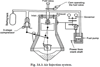
- Advantages: very good atomisation, ability to obtain high mean effective pressure and efficient combustion even with low-grade fuel.
- Disadvantages: requires multistage air compressor and additional mechanical linkages, adding weight, complexity and cost, and incurs power loss to drive the compressor.
Solid (airless) injection systems
In solid injection, liquid fuel is injected directly at high pressure into the combustion chamber without using compressed air for atomisation. These systems are widely used in modern diesel engines.
Common solid-injection system types include:
- Common rail system
- Unit injection system
- Individual pump-and-nozzle (unit pump) system
- Distributor (rotary) system
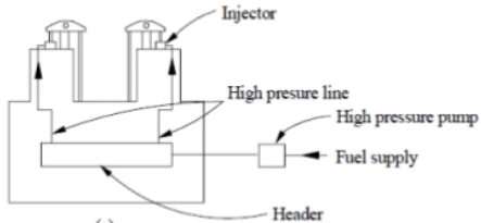
Common rail system
- A high-pressure pump delivers fuel to a common accumulator (rail) where pressure is maintained nearly constant. Injectors at each cylinder are actuated (usually electronically) to control timing and quantity. Metering and timing are controlled at each injector; the system allows flexibility in injection pressure and multiple injection events per cycle.
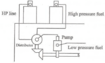
Distributor (rotary) system
- A single high-pressure pump meters and pressurises fuel and supplies it to a rotating distributor which delivers the metered quantity at the correct time to each cylinder. This system achieves uniform distribution and is relatively low cost.
Types of nozzles in injection systems
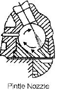
Pintle nozzle
- Pintle nozzles provide good atomisation with reduced spray penetration because the pintle obstructs axial flow and spreads the spray. They are commonly used with pre-combustion chambers and in engines where controlled penetration and mixing are required.
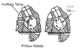
Pintaux nozzle
- A pintaux nozzle is a development of the pintle type with an additional auxiliary hole in the nozzle body to improve cold-start performance and help form a suitable spray pattern for easier ignition.
Comparison: carburetion versus fuel injection
- Both systems aim to prepare a combustible charge consisting of air mixed with atomised fuel.
- In carburetion, atomisation is mainly produced by the air motion in the venturi; air velocity at the nozzle is higher than fuel velocity, and fuel is drawn in and broken into droplets by shear and pressure difference.
- In fluid (mechanical/electronic) fuel injection, fuel is forced at high velocity through a small nozzle so that the fuel's own inertia and nozzle design produce atomisation; injection pressure controls droplet size and spray penetration.
Basic fuel injection equations
Volume of fuel injected per cycle can be expressed as:
Vf = Cd × A × V × t
where:
- Cd = coefficient of discharge of the injector orifice
- A = area of the orifice
- V = velocity of fuel through the orifice
- t = time duration of injection
Velocity of injection
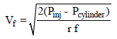
In the usual orifice relation:
- Vf (velocity of injection) depends on the square root of the pressure difference across the injector orifice: this pressure difference is (Pinj - Pcylinder), where Pinj is the injection (pump) pressure and Pcylinder is the instantaneous cylinder pressure opposing injection.
- ρf is the density of the injected fuel used when the inertial flow term is written in mass- or volume-flow expressions.
Time for one injection
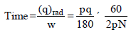

When injection is considered in terms of crankshaft rotation:
- N = engine speed in revolutions per minute (rpm)
- q = crank angle (in degrees) over which injection takes place
- The time for one injection is related to engine speed and the angular duration q; as engine speed increases, the same angular duration corresponds to a shorter time interval.
Operational notes and typical practice
- Carburettors require rich mixtures for cold starts and warm-up because fuel vapour pressure and evaporation are poor at low temperature; devices such as chokes and enrichening circuits are used.
- Acceleration systems (accelerator pump) in carburettors supply an extra squirt of fuel to overcome liquid inertia and prevent momentary leaning during rapid throttle opening.
- Fuel injection provides superior control of quantity, timing and atomisation, improving fuel economy, drivability and emissions; electronic control further allows precise multi-injection events, pilot injections and optimisation across operating conditions.
Summary
Carburetion and fuel injection both serve to supply a combustible air-fuel mixture to the engine. Carburettors rely on air motion and venturi suction to draw and atomise fuel and are simpler but less flexible across wide operating ranges. Fuel injection-especially modern high-pressure common-rail systems-provides precise metering, timing and atomisation, yielding better performance, economy and emissions control. Understanding the governing relations for mass flow, the effect of pressure and density, and practical features such as nozzle lip, altitude compensation and injection timing is essential for design and troubleshooting of these systems.
FAQs on Carburetion & Fuel Injection
| 1. What is carburetion and fuel injection? |  |
| 2. What are the advantages of carburetion over fuel injection? | |
| 3. What are the advantages of fuel injection over carburetion? | |
| 4. Which is more commonly used in modern engines, carburetion, or fuel injection? | |
| 5. Can a carbureted engine be converted to fuel injection? | |


