Mechanism & Machines | Mechanical Engineering SSC JE (Technical) PDF Download
| Table of contents |
|
| Kinematic Link OR Element |
|
| Types of Constrained Motion |
|
| Kinematic Pair and their Classification |
|
| Degree of Freedom |
|
| Simple Mechanism |
|
| Mechanical Advantage |
|
| Solved Numericals |
|

Kinematic Link OR Element
Every part of machine which is having some relative motion with respect to some other part is known as kinematic link .
Types of Links
1. Rigid Link: Deformation is negligible.
2. Flexible Link: Deformation is there but it is in permissible limits.
3. Fluid Link: When motion or power is transmitted in permissible limits.
Mechanism and Machine
- If a number of Kinematic links are assembled in such a way that the motion of one causes constrained and predictable motions to the others it is known as a mechanism.
- A machine is a Practical application of mechanism or a combination of mechanism which, apart from imparting definite motion to the parts, also transmits and modifies the available mechanical energy into some kind of desired work.
Types of Constrained Motion
(i) Completely constrained motion
When motion between two elements of a pair is in a desired/ definite direction irrespective of the direction of force applied. It is known as completely constrained motion.
e.g., sliding pair,
(ii) Successfully constrained motion
When motion between two element of a pair is possible in more than one direction but is made to have motion only in one direction by using some external means, it is called successfully constrained motion.
Example: A piston in a cylinder of an internal combustion engine is made to have only reciprocating motion due to constrain of the piston pin (external), cam and follower, shaft in foot step bearing.
(iii) Incompletely constrained motion
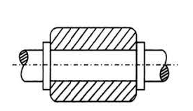
When the motion between the elements of a pair is possible in more than one direction and depends upon the direction of force applied, it is known as incompletely constrained motion e.g. cylindrical shaft in round bearing.
Rigid Body, Resistant Body
- Rigid Body: It does not suffer any distortion under the action of force.
- Resistant Body: Those body which are rigid for the purpose they have to serve for e.g. belt drive, where belt is rigid when subjected to tensile forces.
Kinematic Pair and their Classification
A kinematic pair or simply a pair is a joint of two links having relative motion between them.
(i) According to nature of contact
- Lower Pair: A pair of links having surface of area contact between the members is known as lower pair. Such as, Nut turning on a screw, shaft rotating in a bearing, universal Joint etc.
- Higher Pair: When a pair has a point or line contact between the members is known as a higher Pair. The contact surfaces of two links are dissimilar. Such as, wheel rolling on a surface, cam and follower pair, tooth gears, ball and roller bearings etc.
(ii) According to nature of Mechanical constraint
- Closed Pair: When the elements are geometrically identical, one is solid and full and other is hollow or open. The contact between the two can be broken only by destruction of at least one of the members. All the lower pairs and some of the higher pairs are closed pairs.
- Unclosed Pair: When two links of a pair are in contact either due to forces of gravity or some spring action, is called an unclosed pair.
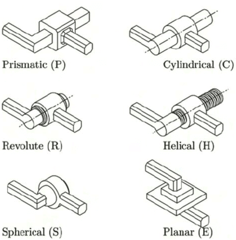
(iii) According to Nature of Relative motion
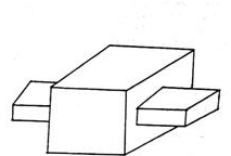
- Sliding Pair: If two links have a sliding motion relative to each other, they form a sliding pair. Such as a rectangular rod in a rectangular hole in a prism is a sliding pair.
- Turning Pair: When one link has a turning or revolving motion relative to the other, they constitute a turning or revolving pair. In slider-crank mechanism, all pairs except the slider and guide pair are turning pairs.
- Rolling Pair: When the links of a pair have a rolling motion relative to each other they form a rolling pair e.g. rolling wheel on a flat surface, ball and roller bearings etc.
- Screw Pair (Helical Pair): If two mating links have a turning as well as sliding motion between them they form a screw pair. The lead screw and the nut of a lathe is a screw pair.
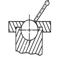
- Spherical Pair: When one link in the form of a sphere turn inside a fixed link, it is a spherical pair.
Degree of Freedom
The minimum number of independent variables required to define the position or motion of the system is known as Degree of freedom. The connection of a link with another imposes certain constrains on relative motion thus.
Degree of freedom = 6 – number of restraints
| Points to Remember |
|
|
|
Degree of Freedom of a Mechanism
Let, F = Degree of freedom (D.O.F.)
L = Total number of links in mechanism
P1 = Number of pair having one D.O.F.
P2 = Number of pair having two D.O.F.
P3 = Number of pair having three D.O.F.
P4 = Number of pair having four D.O.F.
P5 = Number of pair having five D.O.F.
- If in a mechanism one link is fixed then number of movable links = N–1.
- Number of degrees of freedom of (N-1) movable links = 6 (N-1).
- Each pair having one degree of freedom imposes 5 restraints on the mechanism reducing its degree of freedom by 5 P1.
- Each pair having two degrees of freedom will imposes 4 restraints reducing the degrees of freedom of the mechanism by 4P2.
- Similarly other pairs having 3,4 and 5 degrees of freedom reduce the degrees of freedom of the mechanism
- Degree of freedom
6(N – 1) – 5P1 – 4P2 – 3P3 – 2P4 – 1P5
Degree of Freedom of Plane (2d) Mechanism (Grubler Criterion)
Most of the mechanism are two dimensional such as four link or a slider crank mechanism in which displacement is possible along two axes (one restraint) and rotation about only one axis (two restraints). Thus there are three general restraints. Hence.
F = 3(N – 1) – 2P1 – 1P2.
Here, L = Number of link in a mechanism
P1 = Number of pair having one degree of freedom
P2 = Number of pair having two degree of freedom
Kutzback's equation
F = 3(L – 1) – 2j – h
Here, L = Number of link
j = Number of binary joint
h = Number of higher pair
Grubler's Equation
It is for those mechanism which have single degree of freedom and zero higher
pair.
3l – 2j – 4 = 0
Here, l = Number of links
j = Number of binary joints
Degree of Freedom for different frames
F = 0 (Frame)
F < 0 (Redundant frame)
F > 0 (constrained/unconstrained frame)
Simple Mechanism
All the mechanisms having 4-links are simple mechanism and the mechanism having more than 4 links are compound mechanism.
There are three different simple mechanisms.
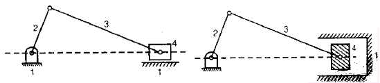
- Four bar mechanism
It consists of four links and four turning pairs. - Slider crank mechanism
It consists of four links, three turning pairs and one sliding pair. - Double slider crank mechanism
It consists four links, two turning pairs and two sliding pairs.
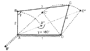
Four-Bar Mechanism
- In a four-link mechanism, a link that makes complete revolutions is the crank, the link opposite to fixed link is the coupler and the fourth link is a lever or rocker if it oscillates or an another crank if rotates.
- Grashof's law: For a continuous relative motion between the links in a mechanism, the summation of shortest and longest link should not be greater then summation of other two link.

- If the sum of the lengths of the largest and shortest links is less than the sum of the lengths of the other two links, the linkage is known as a class - I, four bar linkage.
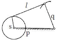
The mechanism is known as a crank-rocker or a crank-lever mechanism or a rotary oscillating convertor.
- If the shortest link is fixed, the adjacent links would make complete revolutions. The mechanism thus obtained is known as crank-crank or double crank or drag-crank mechanism or rotary-rotary converter.
- When link q is fixed then the links 'l' and 'p' would oscillate. The mechanism is known as a rocker-rocker or double rocker or an oscillating-oscillating converter.
- When the sum of the lengths of the largest and shortest links is more than the sum of lengths of the other two links the linkage is known as class - II, four bar linkage.
In such a linkage, the mechanism and its inversions give the same type of locomotive in which the rotary motion of the wheel is transmitted to the other wheel.
Inversion of 4-Bar Mechanism
- Coupling rod of locomotive-Crank-Crank mechanism
- Beam engine - Crank-rocker mechanism
- Watt's indicator - Rocker-Rocker mechanism
Note:
- Approximate straight line mechanism are watts indicator, modified Scott- Russel mechanism, Grass Hopper mechanism.
- Exact straight line mechanism are Peculiar mechanism, Hart mechanism, Scott-Russel mechanism.
Inversion of Slider-Crank Mechanism
- By fixing link 1, links 2 and 4 are made the crank and slider respectively. Its application is in Reciprocating engine and Reciprocating compressor.
- Fixing of link 2 of a slider crank chain results in the second inversion. Its application in whitworth quick-return mechanism and rotary engine.
- By fixing link 3 of the slider crank mechanism, link 2 again acts as a crank and link 4 oscillates. Its applications are oscillating cylinder engine and crank and slotted lever mechanism.
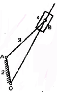
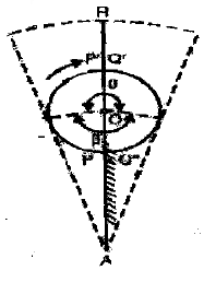
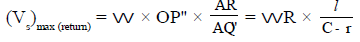
Crank and Slotted Lever Mechanism
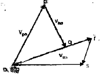
- The angular velocity of the rotating link along with the linear velocity of the slider may be known and it may be required to find the absolute velocity of the slider.
- A crank and slotted-lever mechanism, which is a form of quick-return mechanism used for slotting and shaping machines, depicts the same form of motion.
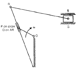
Let,
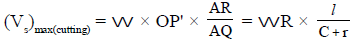
r = length of crank (= OP)
I = length of slotted lever (=AR)
c = distance between fixed centres (=AO)
w = angular velocity of crank
Thus during cutting stroke
- If link 4 of the slider-crank mechanism is fixed, its application in hand pump.
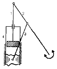
Inversion of Double Slider Crank Mechanism
A four-bar chain having two turning and two sliding pairs such that pairs of the same kind are adjacent is known as a double slider crank chain. The following are its inversions:
First Inversion
- Elliptical trammel
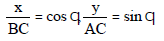
AC = semi-major axes
BC = semi-major axes
x2/(BC)2 + y2/(AC)2 = 1
This is the equation of an ellipse. When C is the mid point of AB, AC = BC then x2 + y2 = AC2 This is the equation of circle with radius (AC = BC).
Second Inversion
If any of the slide block of first inversion is fixed then second inversion is obtained such as scotch yoke mechanism, which is used to convert the rotary motion into a simple harmonic motion.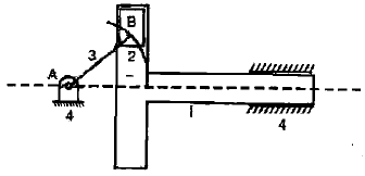
Third Inversion
Oldham coupling: It is used to connect two parallel shafts when the distance between their axes is small.
Maximum sliding velocity
=peripheral velocity along the circular path
=angular velocity of shaft × distance between shafts
Mechanical Advantage
- The Mechanical Advantage (MA) of a mechanism is the ratio of the output force or torque to the input force or torque at any instant.
- Thus for the linkage given in figure. If friction and inertial forces are ignored and the input torque T2 is applied to the link 2 to drive the output link 4 with a resisting torque T4 then
Power input = Power output
T2W2 = T4W4
or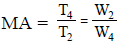
Thus, it is the reciprocal of the velocity ratio.
Solved Numericals
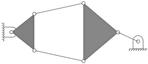
Q1: A five-bar mechanism is shown in the figure. What will be the degrees of freedom of this plane mechanism? 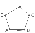
(a) 3
(b) 1
(c) 2
(d) 0
Ans: (c)
Sol:
Concept:
Kutzback equation for DOF is given by
DOF = 3(n - 1) - 2j - h
where n = Number of links, j = Number of joints, h = Number of higher pairs.
Calculation: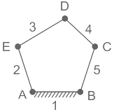
Here, there are 5 links, 5 binary joints
⇒ L = 5, j = 5, h = 0
⇒ n = 3(5 – 1) - 2 (5)
⇒ n = 2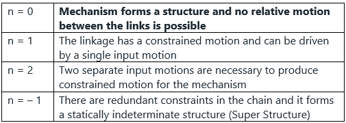
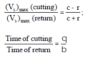
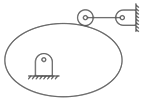
Q2: The degree of freedom of the mechanism shown in the figure is
 (a) two
(b) zero
(c) one
(d) negative one
Ans: (c)
Sol:
Given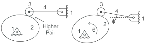 We have N = 4, P1 = 3, P2 = 1, Fr = 1
where Fr = Number of redundant kinematic pair.
Redundant kinematic pair:
The main purpose of the roller follower is to reduce friction. It is not playing any role in the transfer of relative motion. Oscillation of follower ϕ is the function of rotation of cam θ.i.e ϕ = f(θ ). Hence we can say that there is a redundant pair in this mechanism. After considering the redundant pair we shall get a degree of freedom.
F = 3(N - 1) - 2P1 - 1P2 - Fr
Fr = 1, Kinematic pair between roller and cam.
F = 3 × (4 - 1) - (2 × 3) - (1 × 1) - 1 = 1
Hence, the degree of freedom of the mechanism is 1.
Q3: The degrees of freedom of a plane mechanism as shown in the figure is: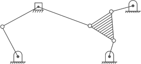 (a)3
(a)3
(b) 4
(c) 2
(d) 1
Ans: (d)
Sol: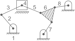
Number of links, N = 8
Number of joint (Having one degree of freedom where rest two degree of freedom is arrested) = j = 10
Now,
F = 3(N - 1) - 2J - h
(No higher pair, h = 0)
F = 3(8 - 1) - 2 × 10
F = 1
Q4: The number of degrees of freedom of the linkage shown in the figure is
(a) -3
(b) -0
(c) 1
(d) 2
Ans: (c)
Sol:
Number of links, N = 6
Total number as binary joints, j = 7
h = 0
F = 3 (N-1) – 2j
= 15-14 = 1.
Q5: Of the kinematic linkage below, the number of degrees of freedom (F) is: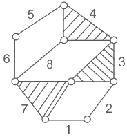
(a) 2
(b) 3
(c) 4
(d) 1
Ans: (d)
Sol:
n = 8, l = 10, h = 0
DOF = 3 (n - 1) - 2l - h
= 3 (8 -1) - 2 (10) - 0
= 21 - 20
DOF = 1
|
6 videos|104 docs|59 tests
|
FAQs on Mechanism & Machines - Mechanical Engineering SSC JE (Technical)
| 1. What is a kinematic pair and how are they classified? |  |
| 2. What is the degree of freedom in a mechanism? | |
| 3. What is mechanical advantage in a mechanism? | |
| 4. What is the difference between a kinematic link and a kinematic element? | |
| 5. Can you provide an example of a simple mechanism? | |


Sample Paper
,Mechanism & Machines | Mechanical Engineering SSC JE (Technical)
,past year papers
,Objective type Questions
,Viva Questions
,MCQs
,Summary
,Free
,Mechanism & Machines | Mechanical Engineering SSC JE (Technical)
,Semester Notes
,Mechanism & Machines | Mechanical Engineering SSC JE (Technical)
,practice quizzes
,Important questions
,video lectures
,Exam
,mock tests for examination
,study material
,ppt
,shortcuts and tricks
,Previous Year Questions with Solutions
,Extra Questions
,


Mechanism & Machines Free PDF Download
Importance of Mechanism & Machines
Mechanism & Machines Notes
Mechanism & Machines Mechanical Engineering Questions
Study Mechanism & Machines on the App
|
© EduRev
|
Education Revolution
|


|


