Cams | Mechanical Engineering SSC JE (Technical) PDF Download
Introduction to CAMS
- A cam is mechanical member used to impart desired motion to a follower by direct contact. The cam may be rotating or reciprocating whereas the follower may be rotating, reciprocating or oscillating.
- They are manufactured usually by die-casting, milling or by Punch Press.
- A cam and follower combination belongs to the category of higher pairs.
Elements of a CAM
- A driver member known as the cam
- A driven member called the follower
- A frame which supports the cam and guides the follower.
Types of CAMS
(i) According to Shape- Wedge and flat cams: A wedge cam has a translational motion. The follower can either translate or oscillate. Instead of using a wedge, a flat plate with a groove can also be used.

- Radial or Disc Cams: A cam in which the follower moves radially from the centre of rotation of the cam is known as a radial or disc cam.

- Spiral cams: A spiral cam is a face cam in which a groove is cut in the form of a spiral. It finds its use in computers.
- Cylindrical cams: In a cylindrical cam, a cylinder which has a circumferential contour cut in surface, rotates about its axis. It is also known as barrel or drum cams.

- Conjugate cams are preferred when the requirements are low wear, low noise, better control of the follower, high speed, high dynamic loads etc.
- Globoidal cams: It has two types of surface i.e. convex or concave. It is used when moderate speed and the angle of oscillation of the follower is large.
(ii) According to the movement of follower
- Rise-Return-Rise (RRR): In this, there is alternate rise and return of the follower with no period of dwells. The follower has a linear or an angular displacement.

- Dwell-Rise-Return Dwell (D-R-R-D): In this cam, there is rise and return of the follower after a dwell.

- Dwell-Rise-Dwell-Return-Dwell (D-R-D-R-D): The dwelling of the cam is followed by rise and dwell and subsequently by return and dwell.

- In case the return of the follower is by a fall, the motion may be known as Dwell-Rise-Dwell (DRD).
 Types of Follower
(i) According to Shape
- Knife-edge follower: Its use is limited as it produces a great wear of the surface at the point of contact.
- Roller follower: At low speeds, the follower has a pure rolling action, but at high speeds, some sliding also occurs. In case of steep rise roller follower is not preferred.
- Mushroom follower: It does not possesses the problem of jamming of the cam. However high surface stresses and wear are quite high due to deflection and misalignment if flat faced follower is used. These disadvantages are reduced if a spherical faced follower is used instead of a flat follower.
(ii) According to movement
- Reciprocating Follower: In this type, as the cam rotates the follower reciprocates or translates in the guides.

- Oscillating Follower: The follower is pivoted at a suitable point on the frame and oscillates as the cam makes the rotary motion.

(iii) According to location of line of movement
- Radial Follower: The follower is known as a radial follower it the line of movement of the follower passes through the centre of rotation of the cam.

- Offset Follower: If the line of movement of the roller follower is offset from the centre of rotation of the cam, the follower is known as an offset of follower.

Terminology of CAM

- Base circle: It is the smallest circle tangent to the cam profile drawn from the centre of rotation of a radial cam.
- Trace Point: It is a reference point on the follower to trace cam profile such as knife edge of a knife, edged follower and centre of the roller of a roller follower.
- Pitch curve: It is the curve drawn by the trace point assuming that the cam is fixed and the trace point of the follower rotates around the cam.
- Pressure angle: The pressure angle, representing the steepness of the cam profile, is the angle between the normal to the pitch curve at a point and the direction of the follower motion. It varies in magnitude at all instants of the follower motion. A high value of the maximum pressure angle is not desired as it might jam the follower in the bearings.
- Pitch Point: It is the point on pitch curve at which the pressure angle is maximum.
- Pitch circle: It is the circle passing through the pitch point and concentric with the base circle.
- Prime circle: The smallest circle drawn tangent to the pitch curve is known as prime circle.
- Dwell is the zero displacement or the absence of motion of the follower during the motion of the cam.
- The motion of the cam can be represented on a graph, the x-axis of which may represent the angular displacement of the cam and the y-axis, the angular or the linear displacement of the follower.
- Angle of Ascent (fa): It is the angle through which the cam turns during the time the follower rise.
- Angle of dwell (d): Angle of dwell is the angle through which the cam turns while the follower remains stationary at the highest or lowest position.
- Angle of Decent (fd): It is the angle through which the cam turns during the time the follower returns to the initial position.
- Angle of Action: It is the total angle moved by cam during the time, between the beginning of rise and the end of return of the follower.
- The dynamic effects of acceleration (jerks) usually, limit the speed of the came.
Solved Numericals
Example 1: Draw the cam profile for following conditions:
Follower type = Knife edged, in-line; lift = 50mm; base circle radius = 50mm; out stroke with SHM, for 600 cam rotation; dwell for 450 cam rotation; return stroke with SHM, for 900 cam rotation; dwell for the remaining period. Determine max. velocity and acceleration during out stroke and return stroke if the cam rotates at 1000 rpm in clockwise direction.
Displacement diagram:
Cam profile: Construct base circle. Mark points 1,2,3…..in direction opposite to the direction of cam rotation. Transfer points a,b,c…..l from displacement diagram to the cam profile and join them by a smooth free hand curve. This forms the required cam profile.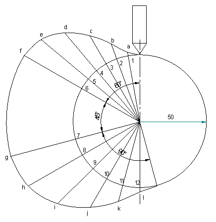
Calculations:
Angular velocity of cam = 
Max. velocity of follower during outstroke = vomax =
 =7857mm/sec =7.857m/sec
Similarly Max. velocity of follower during return stroke = ,vrmax = 
 = 5238mm/sec = 5.238m/sec
Max. acceleration during outstroke = aomax = rω2p (from d3) = 

Similarly, Max. acceleration during return stroke = armax = 

Q2: Draw the cam profile for following conditions:
Follower type = roller follower, in-line; lift = 25mm; base circle radius = 20mm; roller radius = 5mm; out stroke with UARM, for 1200 cam rotation; dwell for 600 cam rotation; return stroke with UARM, for 900 cam rotation; dwell for the remaining period. Determine max. velocity and acceleration during out stroke and return stroke if the cam rotates at 1200 rpm in clockwise direction.
Displacement diagram: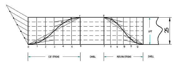
Cam profile: Construct base circle and prime circle (25mm radius). Mark points 1,2,3…..in direction opposite to the direction of cam rotation, on prime circle. Transfer points a,b,c…..l from displacement diagram. At each of these points a,b,c… draw circles of 5mm radius, representing rollers. Starting from the first point of contact between roller and base circle, draw a smooth free hand curve, tangential to all successive roller positions. This forms the required cam profile.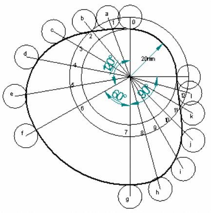
Calculations:
Angular velocity of the cam =
Max. velocity during outstroke = 

Max. velocity during return stroke = 
= 3999.86mm/sec = 3.999m/sec
Acceleration of the follower during outstroke = 

Similarly acceleration of the follower during return stroke = 

Example 3: Draw the cam profile for following conditions:
Follower type = roller follower, off set to the right of cam axis by 18mm; lift = 35mm; base circle radius = 50mm; roller radius = 14mm; out stroke with SHM in 0.05sec; dwell for 0.0125sec; return stroke with UARM, during 0.125sec; dwell for the remaining period. During return stroke, acceleration is 3/5 times retardation. Determine max. velocity and acceleration during out stroke and return stroke if the cam rotates at 240 rpm.
Calculations:
Cam speed = 240rpm. Therefore, time for one rotation =
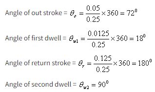
Since acceleration is 3/5 times retardation during return stroke,

Displacement diagram is constructed by selecting ta and tr accordingly.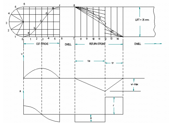 Angular velocity of cam =
Max. velocity of follower during outstroke = 

Similarly Max. velocity during return stroke = 
= 559.9 mm/sec = 0.56m/sec
Max. acceleration during outstroke 

acceleration of the follower during return stroke =  7.17m/sec2
similarly retardation of the follower during return stroke =
mm/sec2 = 11.94m/sec2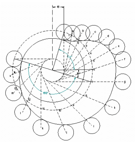
|
5 videos|103 docs|59 tests
|
FAQs on Cams - Mechanical Engineering SSC JE (Technical)
| 1. What is CAMS in mechanical engineering? |  |
| 2. What are the types of CAMS used in mechanical engineering? |  |
| 3. How do CAMS help in the manufacturing process? |  |
| 4. How are CAMS different from CAD software? |  |
| 5. Why is CAMS important in modern mechanical engineering? |  |


