Traffic Engineering - 2 | Civil Engineering SSC JE (Technical) - Civil Engineering (CE) PDF Download

Chapter 3 (Part 2)
TRAFFIC OPERATIONS
Traffic Regulations Traffic regulations and laws cover the following four phases: 1. Driver controls: include driving licenses, driver tests, financial responsibility and civil liabilty. 2. Vehicle controls: Vehicle registration, requirements of vehicles, equipment and accessories, maximum dimensions and weight and inspection of vehicles. 3. Flow Regulations: directions, turning and overtaking etc., signs and signals 4. General controls: to report accidents and recording and disposing traffic violation cases
Total potential confilicts points on 2 lane roads: (Right Angled intersection)
| Regulation | Potential Conflict point | |||
| 2-way | Total | Crossing | Merging | Diverging |
| One Road one-way | 24 | 16 | 16 | 4 |
| other 2-way | 11 | 7 | 7 | - |
| Both Road-way | 6 | 4 | 4 | - |
- The potential conflicts an two-way operation and varying number of lanes are given in the following Table.
| Number of lanes | Number of potential conflicts Both Roads -Two way | |
| Road A | Road B | |
| 2 | 2 | 24 |
| 2 | 2 | 24 |
| 2 | 4 | 32 |
TRAFFIC CONTROL DEVICES
The most common devices are the following: 1. Traffic signs 2. Signals 3. Markings 4. Islands
1. Traffic Signs
- On the kerb roads, the edge of the sign adjacent to the road should not be less than 0.6 m away from the edge of the kerb. On roads without kerbs, the nearest edge may be 2.0 m to 3.0 m from the edge of the carriageway.
- The signs should be mounted on sign posts painted alternately with 25 cm black and white bands.
Traffic signs have been divided into 3 categories: (a) Regulatory signs (b) Warning signs and (c) Informatory signs
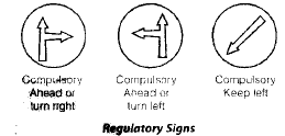
(a) Regulartory Sings
- Regulatory or mandatory signs are meant to inform the road users of certain laws, regulations and prohibitions; the violation of these signs is a legal offence.
- The regulatory signs are classified under the following sub heads:
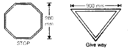
(i) Stop and Give Way Signs
- The stop singn is intended to stop the vehicles on a roadway.
- It is octagonal in shape and red in colour with a white border.
- The give way sign is used to control the vehicles on a road so as to assign right of way to raffic on other roadways.
- This sign is Triangular in shape with the apex downwards and white in colour with a red border.
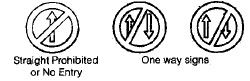
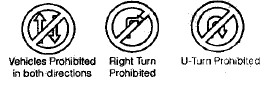
(ii) Prohibitory Signs
- are meant to prohibit certain traffic movements, use of horns or entry of cerain vehicle class.
- Circular in shape and white in colour with a red border.
(iii) No parking and No stopping signs
- is meant to prohibit parking of vehicles at that place.
- circular in shape with a blue background a red border and an oblique red at an angle of 45°
- No stopping/standing is meant to prohibit stoppping of vehicles at that place.
- Circular in shape with Blue background,Red borrder and two oblique red bars at 45° and right angle to each other.
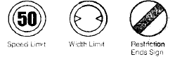
(iv) Speed limit and vehicle control signs
- Speed limit signs are meant to restrict the speed of all or certain classes of vehicles on a particular stretch of a road.
- These signs are circular in shape and white background, red border and black numerals indicating the speed limit.
- The vehicle control signs are circular in shape, red border and balck symbols instead of numerals.
(v) Restriction Ends Sign
- indicates the point at which all prohibitions notified prohibitory sings for moving vehicles ceases to apply
- Circluar in shape with white back ground and broad diagonal black at 45°

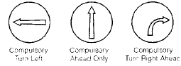
(vi) Compulsory Direction Control Signs
- Indicate by arrows, the appropriate directions in which the vehicles are obliged to proceed.
- Circular in shape with a blue background and white direction arrows.
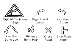
(b) Warning Signs
- Warning or cautionary signs are used to warn the road users of certain hazardous conditions that exist on or adjacent to the roadway.
- The warning signs are in the shape of equilateral triangle with its apex pointing upwards.
- They have a white back ground, red border and black symbols.
- These signs are to be located at sufficient distance in advance of the hazard warned against; these distances are:
| Class of Roads | Distance |
| NH/SH | 120 m |
| MDR | 90 m |
| ODR | 60 m |
| VR | 40 m |
| Urban Roads |

(c) Informatory Signs
- These signs are used guide the road users along routes, inform them of destination and distance and provide with information to make travel easier, safe and pleasant.
- The information signs are grouped under the following subheads:
(i) Direction and place Identification Signs
- are rectangular with white background , black border and black arrows and letters.
- include Destination signs, Direction signs, Route marker and Place identification signs.
(ii) The facility Information signs
- Rectangular in shape with blue bakground and white/black letters symbols.
- Include Public Telephone, Petrol pump, Hostital, first aid post etc.
(iii) Parking signs
- Are set up parallel to the road using square sign board with blue background and white coloured letter 'P'.
(iv) Flood Gauge Sign
- Should be installed at all cause ways.
2. Traffic Signals Advantages Properly designed traffic singnals have the following uses.
1. They provide orderly movement of traffic handling capacity of most of the intersections at grade.
2. They reduce certain types of accidents, notably the right angled collisions.
3. When the signal system is properly coordinated, there is a reasonable speed along the major road traffic.
4. Signals provide a chance to crossing traffic of minor road to cross the path of continuous flow of traffic stream at reasonable intervals of time.
5. Automatic traffic signal may work out tobe economical when compared to manual control.
Disadvantages
1. The real-end collisions may increase.
2. Improper design and location of signals may lead to violations of the control system.
3. Failure of the signal due to electric power failure of any other defect may cause confusion to the road users.
Important terms related to traffic signals
Cycle: The period of time required for one complete sequence of signal indications is called cycle.
Phase: A part of the signal cycle allocated to a traffic movement or a combination of traffic movements is called phase.
Interval: Any of the division of the signal cycle during which signal indications do not change is called the interval.
Type of Traffic Signals: The signals are classified into the following types:
(i) Trafffic control signal (a) Fixed-time signal (b) Manually operated signal (c) Traffic actuated (automatic) singnal
(ii) Pedestrian signal
(iii) Special Traffic Signal
(i) Traffic Control Signals
- have three coloured light glows facing each direction of traffic flow.
- the red light is meant for “stop”, the green light indicates ‘Go’ and the amber light allows the clearance time for the vehicles which enter the intersection area by the end of green time, to clear off.
Fixed time Signal
- The tim ing of ea ch p has e of the c ycle is predetermined based on the traffic studies.
- The main drawback of the signal is that some times the traffic flow on one road may be almost nil and traffic on the cross road may be quite heavy yet as the singal operates with fixed timings, the traffic in the heavy stream will have to stop at red phase.
Traffic Actuated Signals
- are those in which the timings of the phase and cycle are changed according to traffic demand.
TYPE OF TRAFFIC SIGNAL SYSTEM:
Simultaneous System
- All the signals show the same indication at the same time.
- As the division of cycle is also the same at all intersections, this system does not work satisfactorily.
Alternate System
- Alternate group of signals show opposite indications in a route at the same time.
- More satisfactory than simultaneous system
Simple Progressive Systems
- A time schedule is made to permit as nearly as possible a continuous operation of groups of vehicles along the main road at a reasonable speed.
Flexible Progressive System
- In this system it is possible to automatically vary the length of cycle, cycle division and the time schedule at each signalized intersection with the help of a computer.
Do you know?
This is the most efficient system of all the four types described above.
Flashing Beacons
- are meant ot warn the traffic.
- At flashing red signals, the drivers of vehicles shall stop before entering the nearest cross walk at an intersection or at a stop line.
- When marked flashing yellow signals are caution signals meant to signify that drivers may proceed with caution
Design of Isolated Fixed Time Signal
1. Stop time or red phase R, of a signal is the sum of go and clearance intervals or green and amber phases for the cross flow i.e.
G2 + A2 at a two phase signal.
2. Towards the end of red phase, there may be a short duration when the amber lights are put on along with red light signal in order to indicate 'get set' to go.
This phase is the last part of red phase itself, and may be called ‘red-amber’ or ‘initial amber’.
Do you know?
The vehicles are not supposed to cross the stopline during the red amber period.
3. Clearance time is provided just after the green phase before the red phase, to fulfil two requirements.
(a) Stopping time for approaching vehicle to stop at stopline after the signal changes from green to amber.
(b) Clea rance time for app roaching vehicles. Usually 2 to 4 seconds would be suitable for the amber phase.
4. Go time greentime is decided based on the approach volume during peak hour.
DESIGN PROCEDURES
IRC Guidelines
1. The pedestrian green time required are calculated based on walking speed of 12 m/sec. and initial walking time of 7.0 sec.
2. The cycle time is calculated after allowing amber time of 2 sec. each.
3. The minimum green time required for vehicular traffic on any of the approaches is limited to 16 secs.
Road Marking
- Are made of lines, patterns, words, symbols or reflectors on the pavement, kerb side of islands or on the fixed objects within or near the roadway.
- The various types of markings may be classified as,
(a) Pavement Markings
(b) Kerb Markings
(c) Object markings
(d) Reflector unit markings
Pavement Markings
- may be generally of white paint.
- yellow colour markings are used to indicate parking restrictions and for the continuous centre and barrier line markings.
- The width of pedestrain crossing may be between 2.0 and 4.0 depending upon local requirements.
Kerb Markings
- The markings on the kerb are made with alternate black and white line.
Reflector Unit Markings
- Reflector markers are used as hazard markers and guide markers for safe driving during night.
- Hazard makers reflecting yellow light should be visible from distance of about 150 m.
Road Delineators
- Are devices to outline the roadway to provide visual assistance to drivers about the alignment of road ahead, especially at night.
Three types of delineators that may be used are:
1. Roadway indicators
2. Hazard Markers
3. Object Markers
- Roadway indicators are in the form of guide posts 0.08 to 1.0 m high and painted by black and white strips with or without reflectors and are intended to delineate the edges of the roadway.
- Hazard markers are 12 m high plates on posts, either with three red reflectors or markers with black and yellow strips at 45° towards the side of the obstruction.
- Object markers ar circular red reflectors arranged on triangualr or rectangular panels.
Traffic Islands
- Traffic islands are raised areas constructed within the roadway to establish physical channels through which the vehicular traffic may be guided.
- Traffic islands may be classified based on the function as:
1. Divisional islands
2. Channelizing islands
3. pedestrian loading islands
4. Rotary
1. Divisional islands
- Are intended to separate opposing flow of traffic on a highway with four or more lanes.
- By dividing the highway into oneway roadways, the head-on collisions are eliminated and other accidents are also reduced.
2. Channelizing islands
- Are used to guide the traffic into proper channel through the intersection area.
3. Pedestrain loading islands
- Are provided at regular bus stops and similar places for the protection of passengers.
- A pedestrain island at or near a cross walk to aid and protect pedestrain crossing the carriageway may be termed as pedestrain refuse islands.
4. Rotary
- Is the large central island of a rotary intersection; this islands is much larger than the central island of channelized intersection.
- The crossing manoeuvre is converted to wearing by providing sufficient wearing length.
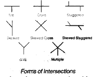
INTERSECTION
Intersections may be classified into two broad groups: 1. Intersection at grade 2. Grade separated intersection
1. Intersection at Grade
- These include all roads which meet at more or less the same level.
- The traffic manoeuvres like merging. diverging and crossing are involved in the intersection at grade.
- These intersections may be further classified as unchannelized, channelized and rotary intersections.
The basic requirements of intersection at grade are:
1. At the intersection the area of conflict should be as small as possible.
2. The relative speed and particularly the angle of approach of vehicle should be small.
3. Adequate approaching should be available for vehicles approaching the intersection.
4. Sudden change of path should be avoided.
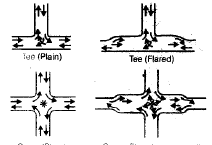
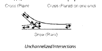
(a) Unchannelized intersections
- The intersection area is paved and there is absolutely no restriction to vehicles to use any part of intersection area.
- When no additional pavement width for turning movement is provided, it is called plain intersection.
- When the pavement is widened at the intersection area, by a traffic lane or more, it is known as flared intersection.
- The conflict area is quite large as path of turning vehicles are not restricted or controlled. One of the crossing vehicles will have to stop while the other proceeds.
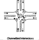
(b) Channelized intersections
- Channeliz ed inters ection is achieved introducing islands into the intersection area, thus reducing the total conflict area available in the unchannelized intersection.
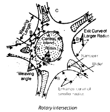
(c) Rotary intersection
- It is an enlarged road intersection where all converging vehicles are forced to move round a large central island in one direction (clockwise direction) before they can weave out of traffic flow into their respective directions.
Design Factors of Rotary
1. Design Speed 40 kmph for rotaries in rural areas 30 kmph for rotaries in urban areas
2. Shape of Central Island
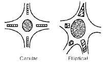
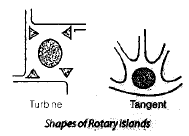
- The shape of central island depends on the number and the layout of the intersecting roads.
- When two equally important roads cross at roughly right angles i.e., all the four radiating roads placed symmetrically, a circular shape is suitable.
- The island may be often elongated to accomodate in the layout four or more intersecting roads; and to allow for greater traffic flow along the direction of elongation.
- Too much elongation and tangent shape are not desirable as there is a tendency of traffic in this direction to move much faster.
- Turbine shape forces reduction in speeds of vehicle entering the rotary and enables speeding up of vehicles going out; however at night, the head light glare is a limitation of the design.
3. Radius of Rotary Roadway

Where, V = design speed of vehicle, kmph
f = coefficient of friction, may be taken as 0.43 and 0.47 for the speeds 40 and 30 kmph respectively, after allowing a factor of safety of 1.5.
- The recommended minimum radii of central island are 1.33 times the radius of entry curves.
- The IRC has suggested the radius of entry curve to be 20 to 35 m and 15 to 25 m for rotary design speeds of 40 and 30 kmph.
4. Wearing angle and weaving distance
- The angle between the path of a vehicle entering the rotary and that of another vehicle leaving the rotary at adjacent road, thus crossing the path of the former is termed as the wearing angle.
- The wearing operation including merging and diverging can take place between the two channelizing islands of the adjacenet intersecting legs and this length of the rotatory roadway is known as weaving length.
- For smooth flow of traffic the weaving angle should be small put not less than 15° as the diameter of central island required will be too large.
- The weaving length should be at least four times the width of weaving section.
The recommended value of weaving length are 45 to 90 m for 40 kmph and 30 to 60 m for 30 kmph design speeds.
5. Width and Radius of Carriageway at entry and exit
- The minimum width of carriageway at the entrance and exit should be 5.0 m.
- Vehicles leaving the rotary would accelerate to the speed of the radiating roads and hence the exit curves should be of a larger radius than entry curves; one and a half to two times radius of entry is considered reasonable.
- The pavement width at entrance curve will be higher than at exit curve as the radius of the former is less than the latter.
6. Other design standards
- The shape and size of channelizing island is governed by the radius of the rotary the radii of the entrance and exit curves and the angles and layout of the radial road and rotary.
- The design of the curve should be made assuming no super elevation.
- The minimum sight distance should be 45 and 30 m for design speeds of 40 and 30 kmph respectively.
CONDITIONS WHEN TRAFFIC ROTARY IS JUSTIFIED
- The lowest limit of traffic volume when a traffic rotary is justified is about 500 vehicles per hour on all intersecting roads put together and the maximum limit beyond which rotary may not efficiency function is about 5000 vehicles per hour.
- IRC suggests that the maximum volume of traffic that a rotary can efficiency handle is 3000 vehicles per hour entering from all the legs of the intersection.
- Traffic rotatery may be provided where the intersecting motor traffic is about 50 percent or more of the total traffic on all intersecting roads or where the fast traffic turning right is as least as 30 percent of the total traffic.
ADVANTAGES AND LIMITATIONS OFTRAFFIC ROTARY
1. Crossing manoeuvre is converted into weaving or merging and diverging operations.
2. The variable cost of operation of automobile is less at a traffic rotary than at a signalized intersection where the vehicles have to stop and proceed.
3. The possible number of accidents and the severity of accidents are quite low because of low relative speed.
4. Rotaries can be constructed with advantage when the number of intersecting roads is between four and seven.
5. The capacity of the rotary intersection is the highest of all other intersections at grade.
Limitation
1. Rotary requires comparatively a large area of land and so where space is limited and costly as in built up areas, the total cost may be very high.
2. Where pedestrian traffic is large as in urban areas the rotary by itself cannot control the traffic and hence has to be supplemented by traffic police.
3. Where the angle of intersection of two roads is too acute or when there are more than seven intersecting roads, rotatery are unsuitable.
GRADE SEPARATED INTERSECTIONS
- The intersecting roads are separated by difference in level, thus eliminating the crossing manoeuvres.
- The grade separation may be either by an overbridge or an under pass.
- Transfer of route at the grade separation is provided by interchange facilities consisting of ramps.
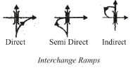
- Interchange ramps may be classified as direct, semidirect or indirect.
- The direct interchange ramp involve diverging to right side and merging from the right.
- S emidir ect interchang e ramp allow s diverging to left but merging is from right side.
- In the indirect method of interchange ramp, a simple diverging to the left and a merging from the left side are involved which are simpler and less hazardous than diverging to the right and merging from right; but the distance to be traversed in indirect interchange is more.
Advantages of Grade Separation
1. Maximum facility is given to the crossing traffic.
As the roads are separate, this avoids necessity of stopping and avoids accidents while crossing.
2. There is increased safety for turning traffic and by indirect interchange ramp even right turn movement is made quite easy and safe by converting into diverging to left and merging from left.
3. The capacity of the grade operated intersection can practically approach that of the two cross roads.
4. It is possible to adopt grade separation for all likely angles and layout of intersecting roads.
Disadvantages
1. It is very costly to provide complete grade separation and interchange facilities.
2. Where there is a limited right of way like built up or urban area or where the topography is not favorable, construction of grade separation is costly, difficult and undesirable.
3. In flat or plain terrain, grade separation may introduce undesirable crests and sags in the vertical alignment.
Grade Separation Structures
- The grade separated intersections are classified as over-pass and under pass.
- When the major highway is taken above by raising its profile above the general ground level by embankment and an overbridge across another highway, it is called an over-pass.
- If the highway is taken by depressing it below the ground level to cross another road by means of an under-bridge, it is known as under-pass.
- The choice of the over-pass or under-pass depends on topography, vertical alignment, drainage, economy, aesthetic features and preferential aspects for one of the highways.
Advantages of Over-pass
1. Troublesome drainage problems may be reduced by taking the major highway above the cross road.
2. For the same type of structure when the wider road is taken above the span of the bridge being small, the cost of the bridge structure will be less.
3. In an over-pass of major highway, there is an aesthetic preference to the main through traffic and less feeling of restriction or confinement when compared with the under-pass.
4. Fu tur e expansion or lat eral expansion or construction of separate bridge structure for divided highway is possible.
Disadvantages of Over-pass
1. In rolling terrain if the major road is to be taken above, the vertical profile will also have rolling grade line.
2. If the major highway is to be taken over by constructing high embankments and by providing steep gradients, the increased grade resistance may cause speed reduction on heavy vehicles.
Here will be restrictions to sight distance unless long vertical curves are provided.
Advantages of an Underpass
1. The is a warning to traffic in advance due to the presence of an under pass which can be seen from distance.
2. When the major highway is taken below, it is advantageous to the turning traffice because the traffic from the cross road can accelerate while descending the ramp to the major highway and the traffic from the major highway can deacelerate while ascending the ramp to the cross roads.
3. The under-pass may be of advantage when the main highway is taken along the existing grade without alteration of its vertical alignment and cross road is depressed and taken underneath.
Disadvantage of an Underpass
1. There may be troublesome drainage problems at the under pass, especially when the ground water level rises high during rainy season.
2. At under-pass the over head structure may restrict the vertical sight distance even at the valley curve near the under-pass.
3. There is a feeling of restriction to the traffic at the sides while passing along the under-pass and unless the clearance is sufficiently large, this may affect the capacity at the intersection.
4. There is no possibility of stage construction for the bridge structure at the under-pass.
Lighting Layouts
1. Single side lighting is economical to install; but is suitable only for narrow roads. For wider roads with 3 or more laws the staggered system or the central lighting system may be adopted.
2. Lights are installed at closer spacings on curvces than on straights. The lights are located on the outer side of the curves to provide better visibility.
3. At summit curve lights should be installed at closer intervals near the summit.
4. For simple intersections, in urban area, the illumination should be at least equal to the sum of illumination values for two roads which form the intersection.
- Spacing between lighting units

- Average maintenance factor may be assumed = 0.8.
|
2 videos|133 docs|55 tests
|


Traffic Engineering - 2 | Civil Engineering SSC JE (Technical) - Civil Engineering (CE)
,Summary
,Traffic Engineering - 2 | Civil Engineering SSC JE (Technical) - Civil Engineering (CE)
,practice quizzes
,MCQs
,Objective type Questions
,Extra Questions
,shortcuts and tricks
,mock tests for examination
,video lectures
,Viva Questions
,ppt
,past year papers
,Previous Year Questions with Solutions
,Free
,Exam
,Sample Paper
,study material
,Traffic Engineering - 2 | Civil Engineering SSC JE (Technical) - Civil Engineering (CE)
,Important questions
,Semester Notes
;


Traffic Engineering - 2 Free PDF Download
Importance of Traffic Engineering - 2
Traffic Engineering - 2 Notes
Traffic Engineering - 2 Civil Engineering (CE) Questions
Study Traffic Engineering - 2 on the App
|
© EduRev
|
Education Revolution
|


|


