Well Hydraulics | Civil Engineering SSC JE (Technical) - Civil Engineering (CE) PDF Download

Chapter 4:
Well Hydraulics
SPECIFIC YIELD (Sy) :
The specific yield of an unconfined aquifer is the ratio of volume of water which will flow under saturated condition due to gravity effects to the total volume of aquifer (V).
where, VWY = Volume of water yielded under gravity effect and V = Total volume of water.
SPECIFIC RETENTION:
The specific retention of an unconfined aquifer is the ration of volume of water retained against gravity effect to the total volume of aquifer (V)

where Vwr = Volume of water retained under gravity effect
Remember:-
Sy +SR=n where, n = porostiy
COEFFICIENT OF TRANSMISSIBILITY:
T=kH
where,
H = Thickness
K = Coefficient of permeability
UNCONFINED AQUIFER:
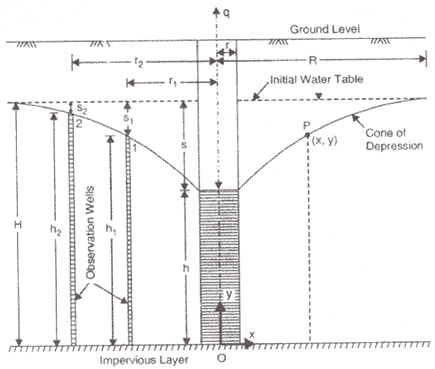
(a) Theims Theory
Where,
q = Rate of flow in m3/s
h1 = Height of water table of 1st observation well
h2 = Height of water table of 2nd observation well
s1 = Drawdown of 1st test well
s2 = Drawdown of 2nd test well.
h1 + s1 = h2 + s2
S1 = Drawdown of 1st test well
S2 = Drawdown of 2nd test well
r1 and r2 are radius of 1st and 2nd observation wells respectively.
(b) Dupits Theory:
where, S = Drawdown in the well
K = Permeability coefficient in m/s.
R = Radius of influence in ‘m’
150m ≤ R ≤ 300m
r = Radius of test well in ‘m’.
Results of dupits theory are not accurate because ‘R’ is based on empirical relation.
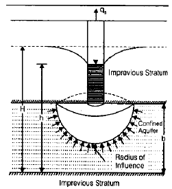
CONFINED AQUIFER:
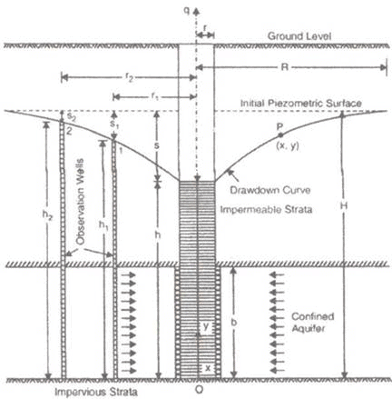
(i) Theims theory: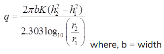
(ii) Dupits theory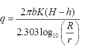
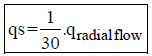
SPHERICAL FLOW THROUGH WELL
qs=k2πrs, R = Radius of well
S = Drawdown
qs = Rate of flow through spherical well in m3/s
PUMPING-IN-TEST
(a) Open end test

where, r = radius of pipe, h = head of water above the base of pipe, it may include gravity head and pressure head.
(b) Tacker test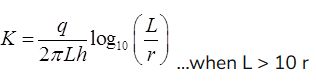
where, L = Length of perforated section of pipe
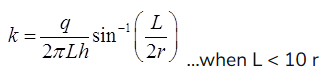
r = Radius of pipe
h = head of which water is added
OPEN WELL (RCUPERATION TEST):
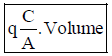
where,
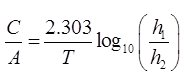
Volume = A. H
A = Area of well
C/A = specific yield or specific Capacity of an open well.
T = Time in ‘sec’
h1 = Position of water table of t = 0
h2 = position of water table of t = T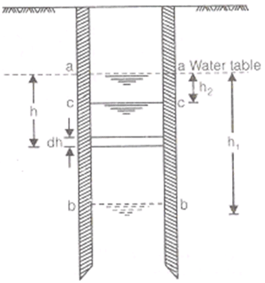
VALUES OF PERMEABILITY:
| SOIL | K (cm/sec) | Degree of permeability | |
| 1. | Coarse Gravel | >1 | High |
| 2. | Fine gravel-Fine sand | 1 to 10-2 | medium |
| 3. | Silt-Sand admixtures,loose silts, rock flour and loess | 10- 2 to 10-4 | Low |
| 4. | Dense slit, clay silt admixutures,non-homogenous clays | 10-4 to 10-6 | Very low |
| 5. | Homogenous clays | < 10-6 | Impervious |
|
2 videos|133 docs|55 tests
|
FAQs on Well Hydraulics - Civil Engineering SSC JE (Technical) - Civil Engineering (CE)
| 1. What is well hydraulics in civil engineering? |  |
| 2. How does well hydraulics impact groundwater extraction? | |
| 3. What are the key parameters considered in well hydraulics analysis? | |
| 4. How is well efficiency calculated in well hydraulics? | |
| 5. What are the common challenges faced in well hydraulics analysis? | |


mock tests for examination
,Semester Notes
,practice quizzes
,Viva Questions
,past year papers
,ppt
,Sample Paper
,study material
,video lectures
,Well Hydraulics | Civil Engineering SSC JE (Technical) - Civil Engineering (CE)
,MCQs
,Important questions
,Previous Year Questions with Solutions
,Objective type Questions
,Free
,shortcuts and tricks
,Well Hydraulics | Civil Engineering SSC JE (Technical) - Civil Engineering (CE)
,Well Hydraulics | Civil Engineering SSC JE (Technical) - Civil Engineering (CE)
,Extra Questions
,Summary
,Exam
,


Well Hydraulics Free PDF Download
Importance of Well Hydraulics
Well Hydraulics Notes
Well Hydraulics Civil Engineering (CE) Questions
Study Well Hydraulics on the App
|
© EduRev
|
Education Revolution
|


|


