Two Port Network - 1


Two Port network
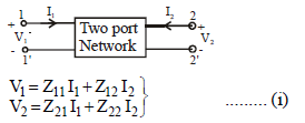
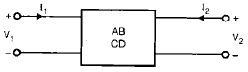
A port is a pair of terminals through which current may enter or leave a network. Two-terminal elements such as resistors, capacitors and inductors form one-port networks. A two-port network is an electrical network having two distinct ports (two terminal pairs) that serve as access points for an input and an output. The current entering one terminal of a port leaves the other terminal of that same port. Three-terminal devices (for example, transistors) or larger networks can be represented as two-port networks by appropriate connections.
When the network is linear, it is possible to fully characterise its behaviour by a small set of parameters obtained from voltage and current measurements at the ports. These parameters permit prediction of how the two-port will interact with other circuits.
Network parameters
- Z-parameters (impedance parameters)
- Y-parameters (admittance parameters)
- ABCD parameters (transmission parameters)
- A' B' C' D' (inverse transmission parameters)
- h-parameters (hybrid)
- g-parameters (inverse hybrid)
Z-parameters
The Z-parameters relate port voltages to port currents by linear equations in the form
V1 = Z11 I1 + Z12 I2
V2 = Z21 I1 + Z22 I2
In matrix notation,
[V] = [Z][I], where [V] = [V1 V2]ᵀ, [I] = [I1 I2]ᵀ and [Z] = [[Z11 Z12] [Z21 Z22]].
The Z-parameters are obtained using open-circuit conditions at the other port:
- Z11 is the input driving-point impedance at port 1 with port 2 open (I2 = 0)
- Z22 is the output driving-point impedance at port 2 with port 1 open (I1 = 0)
- Z12 is the reverse transfer impedance: the ratio V1/I2 with I1 = 0 (port 1 open)
- Z21 is the forward transfer impedance: the ratio V2/I1 with I2 = 0 (port 2 open)

...the input driving-point impedance with the output port open-circuited

...the reverse transfer impedance with the input port open-circuited

...the forward transfer impedance with the output port open-circuited

...the output driving-point impedance with the input port open-circuited
The Z-parameter equations can be rearranged to show an equivalent circuit representation in terms of series impedances and current-controlled voltage sources (CCVS). Rewriting the first equation gives an alternative grouping useful for drawing the equivalent circuit:
V1 = (Z11 - Z12) I1 + Z12 (I1 + I2)
V2 = (Z21 - Z12) I1 + (Z22 - Z12) I2 + Z12 (I1 + I2)
- The terms Z12I2 and Z21I1 act as CCVS elements in the equivalent circuit representation.
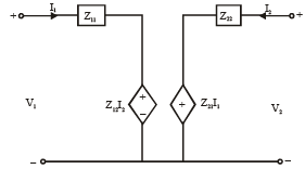
Equivalent circuit for the rearranged Z-equations (one possible representation).
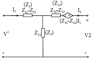
Another equivalent circuit showing series and controlled sources.
Condition of reciprocity and symmetry (Z-parameters)
- Reciprocal network: A two-port is reciprocal when the transfer impedances are equal: Z12 = Z21. In passive reciprocal networks this follows from the symmetry of the network.
- Symmetrical network: A two-port is symmetrical when its input and output driving-point impedances are equal: Z11 = Z22.
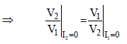
Illustration related to reciprocity and symmetry conditions (Z11 = Z22 for symmetry).
Y-parameters
The Y-parameters (admittance parameters) relate port currents to port voltages by
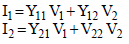
I1 = Y11 V1 + Y12 V2
I2 = Y21 V1 + Y22 V2
In matrix form, [I] = [Y][V].
The Y-parameters are measured with the other port short-circuited (V = 0):
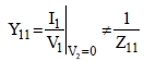
- Y11 is the input driving-point admittance at port 1 with port 2 shorted (V2 = 0)
- Y22 is the output driving-point admittance at port 2 with port 1 shorted (V1 = 0)
- Y12 is the reverse transfer admittance: I1/V2 with V1 = 0 (port 1 shorted)
- Y21 is the forward transfer admittance: I2/V1 with V2 = 0 (port 2 shorted)
...input driving-point admittance (Y11), measured with the output port short-circuited

...reverse transfer admittance (Y12)

...forward transfer admittance (Y21)

...output driving-point admittance (Y22)

Equivalent circuit for Y-parameters
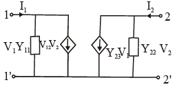
An equivalent pi or tee network may be drawn to represent the Y-parameter relations by splitting Y11, Y22 and mutual admittance terms.
- Rewriting the Y-equations to show admittance branches and mutual branches gives a representation useful for current-source and admittance-network thinking.
For example, the currents may be regrouped as
I1 = (Y11 + Y12) V1 - Y12 (V1 - V2)
I2 = (Y22 + Y12) V2 - Y12 (V2 - V1)
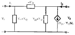
Equivalent circuit for these Y-parameter groupings (showing shunt admittances and mutual admittance branch).
- Reciprocity: For reciprocal networks Y12 = Y21.
- Symmetry: For symmetrical networks Y11 = Y22.
Transmission parameters (ABCD)
Transmission (ABCD) parameters relate the port variables so that the input (port 1) quantities are expressed in terms of the output (port 2) quantities. One commonly used sign convention writes
V1 = A V2 + B (-I2)
I1 = C V2 + D (-I2)
or in matrix form, [V1 I1]ᵀ = [ [A B] [C D] ] [V2 -I2]ᵀ.
The transmission parameters are determined under particular terminal conditions:
- A = V1/V2 with I2 = 0 (receiving end open-circuited)
- B = V1/ (-I2) with V2 = 0 (receiving end short-circuited)
- C = I1/V2 with I2 = 0 (receiving end open-circuited)
- D = I1/ (-I2) with V2 = 0 (receiving end short-circuited)

...A is the reverse voltage ratio with the receiving end open-circuited

...C is the transfer admittance with the receiving end open-circuited

...B is the transfer impedance with the receiving end short-circuited

...D is the reverse current ratio with the receiving end short-circuited
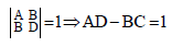
Condition for reciprocity and symmetry (ABCD)
- Reciprocity: A two-port described by ABCD parameters is reciprocal if the determinant of the A-matrix equals 1, that is AD - BC = 1.
- Symmetry: The network is symmetrical if A = D.
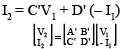
Inverse transmission parameters (A' B' C' D')
The inverse transmission parameters express the output port variables in terms of the input port variables. Using the same sign convention for port currents,
V2 = A' V1 + B' (-I1)
I2 = C' V1 + D' (-I1)
The inverse parameters are obtained similarly by applying the appropriate open- and short-circuit conditions at the sending end:

...A' is the forward voltage ratio with the sending end open-circuited

...C' is the transfer admittance with the sending end open-circuited

...B' is the transfer impedance with the sending end short-circuited

...D' is the forward current ratio with the sending end short-circuited
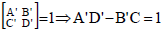
Condition of reciprocity and symmetry (inverse parameters)
- Reciprocity: For the inverse transmission set the corresponding determinant condition AD - BC = 1 carries through to the inverse representation appropriately.
- Symmetry: For inverse parameters the network is symmetrical when A' = D'.
Notes and practical remarks
- Choice of parameter set depends on the application: Z and Y are convenient for series/shunt connections, ABCD parameters are convenient for cascaded two-ports (they multiply), while h-parameters are often used for transistor models at low frequencies.
- Measurement conditions must be respected: Z-parameters use open-circuit at the opposite port, Y-parameters use short-circuit, and ABCD definitions depend on the particular open/short conditions indicated in their definitions.
- Reciprocity is a property of reciprocal (non-gyrator) networks; many passive linear networks built from resistors, capacitors, inductors and mutual inductances are reciprocal. Active devices or those with magnetic bias (gyrators) can break reciprocity.
- Symmetry is a special case of reciprocity where the two ports are identical in their driving-point behaviour.
Summary
This chapter introduced two-port networks and the common parameter sets used to represent them: Z, Y, ABCD and inverse ABCD. Each parameter set has a clear physical meaning tied to specific measurement conditions (open or short at the other port). Conditions for reciprocity and symmetry are stated for each parameter set. Equivalent circuit forms illustrate how controlled sources and series/shunt elements represent mutual interaction between ports.
FAQs on Two Port Network - 1
| 1. What is a two-port network in electrical engineering? |  |
| 2. How can a two-port network be represented mathematically? | |
| 3. What are the applications of two-port networks? | |
| 4. How can we analyze a two-port network? | |
| 5. What is the significance of input and output impedance in a two-port network? | |


 | Explore Courses for Electrical Engineering (EE) exam |
 | Get EduRev Notes directly in your Google search |