Thyristor Commutation - Electrical Engineering (EE) PDF Download

Thyristor Commutation

The process of turning off the thyristor is termed as commutation. Special circuitry is employed for commutation of thyristor. A conducting thyristor can be turned off by natural or forced commutation.

1. Natural Commutation :

The thyristor current is reduced to zero due to the natural characteristics of the input voltage. The device is turned off due to natural behaviour of the source voltage with AC input voltage. Thyristor current goes through a natural zero and a reverse voltage appears across thyristor, hence, thyristor is turned off automatically due to natural behaviour of source voltage.
This method is used in
1. A.C. voltage controllers
2. Phase controlled rectifiers
3. Cycloconverters.
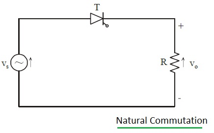
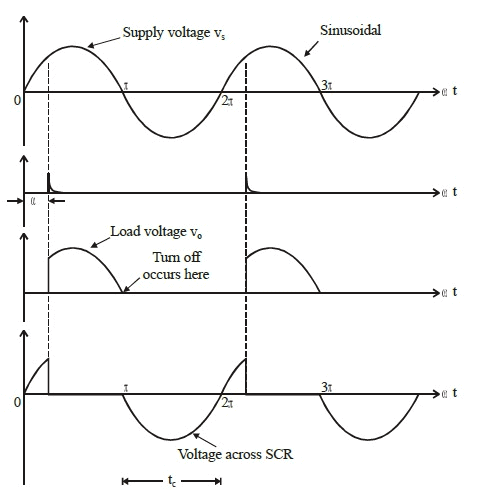
Thyristor Commutation - Electrical Engineering (EE)

Thyristor Commutation - Electrical Engineering (EE)


2. Forced Commutation :

The thyristor current is reduced to zero by an additional circuit called a commutation circuit and turn off process depends on the load current.

Various types of forced commutation are
1. Self commutation
2. Complementary pulse commutation
3. Resonant commutation
4. Auxiliary commutation
5. Line commutation

(1) Self Commutation :

The circuit arrangement is as shown in figure.
When the thyristor is triggered, the capacitor is charged to a voltage higher than the supply voltage. At this instant, the current in the circuit is forced to turn-off the thyristor as the direction of current is reversed. 

Thyristor Commutation - Electrical Engineering (EE)
Thyristor Commutation - Electrical Engineering (EE)Thyristor Commutation - Electrical Engineering (EE)


(2) Complementry Pulse Commutation :

An auxiliary thyristor is used to turn off the main thyristor. The circuit is shown in figure. When Tis fired current flows through R2. At the same time, C is charged by CR1 combination. When Tis fired and conducts C discharges making cathode positive and anode negative. In this case the circuit is completed via R1 and capacitor gets charged through CR2 combination with the polarity opposite to the previous case. This cycle repeats alternately. 

Thyristor Commutation - Electrical Engineering (EE)


(3) Resonant Commutation :

A parallel resonant circuit is used in the circuit, as shown in figure. The capacitor is charged initially with the polarities as shown. As the thyristor is turned on, two currents flow, a load current through the external circuit and pulse of current through LC circuit in the opposite direction. As the current through LC circuit (the discharge current) equals load current, thvristor turns-off. 

Thyristor Commutation - Electrical Engineering (EE)


(4) Auxiliary Commutation :

An auxiliary thyristor is used to turn-off the main thyristor, as shown in figure. Auxiliary thyristor ThA is triggered first so that the capacitor is charged with the polarities as shown. When C is fully charged to Vs ThA is turned-off naturally. When the main thyristor Thm is triggered the capacitor discharges through D, and its polarities reverse. Discharge of capacitor in reverse direction is prevented by D and commutation is achieved. 

Thyristor Commutation - Electrical Engineering (EE)


(5) Line Commutation :

In case of AC supply to the thyristor voltage is applied to it during the negative half cycle. If the duration of the negative cycle is longer than the turn- off time, the thyristor is turned off.

The document Thyristor Commutation - Electrical Engineering (EE) is a part of Electrical Engineering (EE) category.
All you need of Electrical Engineering (EE) at this link: Electrical Engineering (EE)

Top Courses for Electrical Engineering (EE)

FAQs on Thyristor Commutation - Electrical Engineering (EE)

1. What is thyristor commutation in electrical engineering?
Ans. Thyristor commutation in electrical engineering refers to the process of turning off a thyristor by redirecting the current flowing through it. This is essential for controlling power in various applications, such as motor drives and power converters.
2. How does thyristor commutation work?
Ans. Thyristor commutation works by applying a reverse voltage across the thyristor. This reverse voltage reduces the anode current below the holding current, thus turning off the thyristor. Different commutation techniques, such as forced commutation and line commutation, can be used to achieve this.
3. What are the different methods of thyristor commutation?
Ans. There are primarily three methods of thyristor commutation: 1. Forced commutation: In this method, an external circuit is used to redirect the current and turn off the thyristor. Common techniques include using an inductive load or a capacitor in parallel with the thyristor. 2. Line commutation: Line commutation relies on the natural variations in the power system, such as the alternating current waveform, to turn off the thyristor. This method is commonly used in AC voltage controllers. 3. Load commutation: Load commutation involves using the load itself to redirect the current and turn off the thyristor. This method is commonly used in DC motor drives, where the back EMF of the motor plays a crucial role in commutation.
4. What are the advantages of thyristor commutation?
Ans. Thyristor commutation offers several advantages in electrical engineering applications: - Efficient power control: Thyristors allow precise control over power flow, making them suitable for applications that require accurate power modulation. - High reliability: Thyristors are known for their robustness and reliability, making them suitable for demanding industrial environments. - Compact size: Thyristors are compact in size, allowing for space-saving designs in various electrical systems. - Cost-effective: Thyristors are cost-effective compared to other power control devices, making them a popular choice in many industries. - Easy integration: Thyristors can be easily integrated into existing electrical systems, making them a versatile choice for retrofitting or upgrading.
5. What are some common applications of thyristor commutation in electrical engineering?
Ans. Thyristor commutation finds applications in various electrical engineering domains, including: - AC voltage controllers: Thyristors are used to control the voltage supplied to AC loads, allowing for precise regulation and power modulation. - Motor drives: Thyristors are used in DC motor drives to control the speed and direction of the motor. - Power converters: Thyristors are used in power converters to convert AC power to DC power or vice versa, enabling efficient power transmission and distribution. - HVDC transmission systems: Thyristors are used in high-voltage direct current (HVDC) transmission systems to convert and control the flow of power between AC grids. - Uninterruptible power supplies (UPS): Thyristors are used in UPS systems to regulate and stabilize the power supply during power outages or fluctuations.
Download as PDF
Explore Courses for Electrical Engineering (EE) exam

Top Courses for Electrical Engineering (EE)

Signup for Free!
Signup to see your scores go up within 7 days! Learn & Practice with 1000+ FREE Notes, Videos & Tests.
10M+ students study on EduRev
Related Searches

practice quizzes

,

Important questions

,

ppt

,

Thyristor Commutation - Electrical Engineering (EE)

,

shortcuts and tricks

,

Semester Notes

,

pdf

,

MCQs

,

past year papers

,

Extra Questions

,

mock tests for examination

,

Sample Paper

,

Summary

,

video lectures

,

Free

,

Thyristor Commutation - Electrical Engineering (EE)

,

study material

,

Exam

,

Viva Questions

,

Previous Year Questions with Solutions

,

Objective type Questions

,

Thyristor Commutation - Electrical Engineering (EE)

;